ilmenator
-
Posts
2,305 -
Joined
-
Last visited
-
Days Won
37
Content Type
Profiles
Forums
Blogs
Gallery
Everything posted by ilmenator
-
Die Idee ist gut, aber alle Errungenschaften der letzten Jahre werden mit diesem Design über Bord geworfen. 1) zweireihige, verpolungssichere Wannenstecker für die Verbindung zum J8/J9 des Core-Boards, die das DOUT-Signal gleich mit durchschleifen 2) Beschriftung der einzelnen Input-Pins 3) Vs für jeden Block von Input-Pins, also statt 2x4 --> 2x5 4) idealerweise ausreichend Platz für ordentliche, verpolungssichere Wannenstecker auch für die Verbinding der Eingangspins (denn die Tasten/Encoder müssen ja irgendwie verbunden werden, und vermutlich sitzen sie auf einer weiteren Platine)
-
I think one of the essential questions to ask first would be: which button caps can be used with these?
-
Yummi - now if there only were OLED 7-segments for the TPD!
-
On my build, the cable running from the SEQv4 control surface to the BLM16x4 board is around 25cm long, the one going from the BLM16x4 board further on to the TPD board is around 50cm. No problem here so far.
-
RTFM strikes again - I was pretty sure something like that was implemented, but I didn't see this in the docu... my bad!
-
Yes, that's what I am doing, too - I just thought there might be a smarter way than plugging and unplugging USB cables. E.g. pressing and holding the "User" button on the Discovery board while powering up the unit... :smile:
-
I can't find a jumper on the STM32F4 core board for the bootloader hold mode - what is the easiest way to get my core board back to life after it crashes with a hard fault during init? Thanks, ilmenator
-
I wonder why China should be preferred - I don't necessarily agree. What I know is that their price tags are waaayyyy above the other alternatives discussed further up. Anyways, this posting rather looks like self-advertisement...
-
What are the "real" measurements?
-
May I sell my 303 clone with integrated MBSEQ?
ilmenator replied to sylwester's topic in Sale Requests
Yes, one-offs are no problem at all. -
It seems like you forgot to add VAT. Also, availability of the knobs in your first link is: 4 (four!). For the second it's 60. That doesn't really get you very far. Have you checked lead times with TME?
-
No problem, it's always good to have a second pair of eyes looking at the details! If I go for this option (not sure yet, the alternative is an RGB LED matrix module that consumes a little less front panel space) I might revise the pads.
-
It's the same as on my and it works ok there :smile:
-
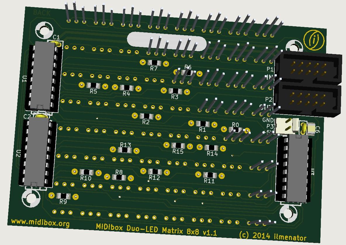
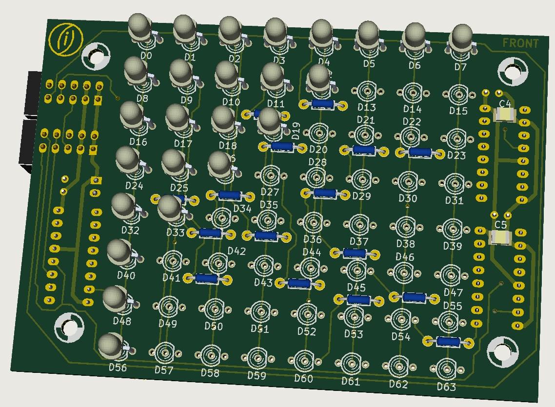
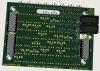
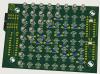
A little update: I have received the second version prototype PCB of the FPGA board, the "heart" of the MIDI matrix. A quick test revealed that the communication works as expected, and I get feedback from the FPGA board to the core about input and output activity of the MIDI ports. Next on the list is an activity display board, essentially an 8x8 Duo LED matrix board. The first seven rows will indicate MIDI port activity, the last row will display "virtual port" activity, e.g. activity of the mergers. This board might also be used by other projects that require some form of Duo LED matrix. It is located anywhere in the DIN/DOUT SR chain and connects to J8/J9 of the core board.
-
Just see this is all 2x20 - I was reading 2x24 which is what I could use... So, sorry not for me.
-
How much?
-
Check the datasheet and compare with the "regular" displays!
-
It means that the shop has to (manually) turn around the panel, re-adjust it, and then do some machining on the backside. You add manual work for them, you have to pay them...
-
Add some fresh solder first, like if you wanted to solder the part - then remove the solder with whatever tool you have (solder sucker, braid, de-soldering gun...).
-
Was genau läuft denn nicht?
-
Oscillator troubles (was: Re: SID as a drum machine?)
ilmenator replied to TK.'s topic in MIDIbox SID
Good find! -
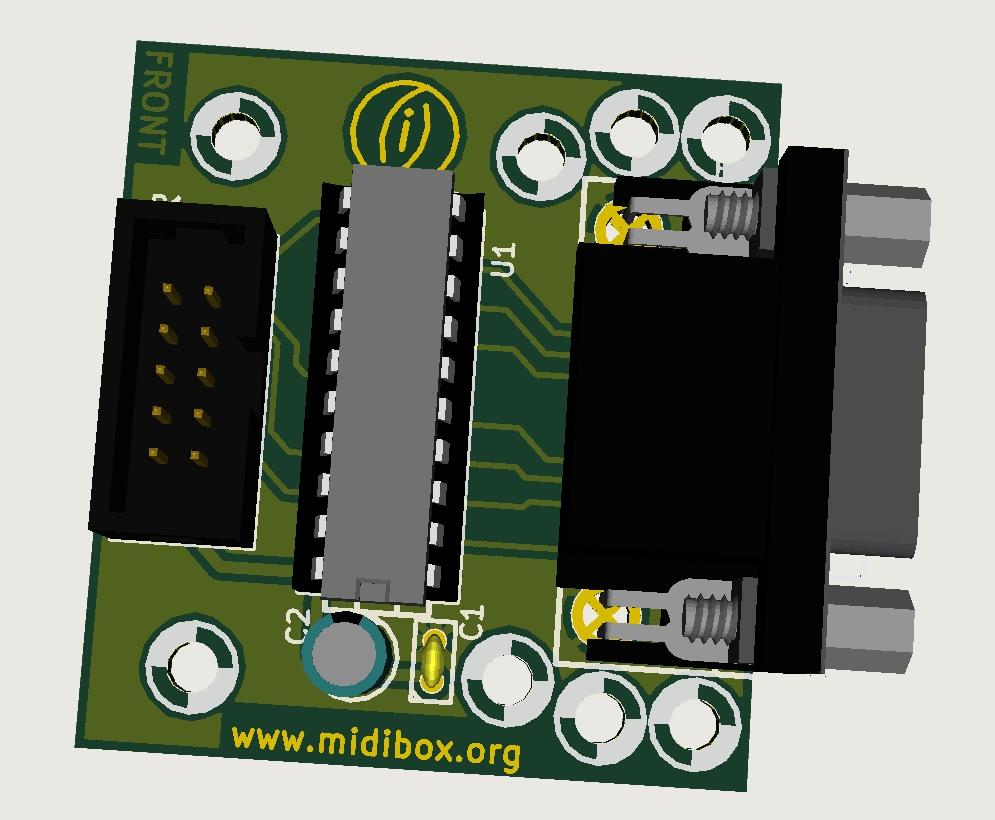
If you want all MIDI ports on the back of your rack enclosure then you might want to think about using SmashTV's MIDI I/O board for that, as the BOB has MIDI sockets on two opposite sides. Take a look in the Wiki and at the BOB section and you can already see what kind of documentation will go there. Schematics will be available, and I am planning to provide PCBs to those interested - together with the BOM it should then be very easy to build your own MIDIbox Matrix. I will also provide the design files for the acrylic enclosure of the BOBs. I'll reveal the FPGA daughterboard details once the MIDI activity display has been tested on the next FPGA board iteration.
-
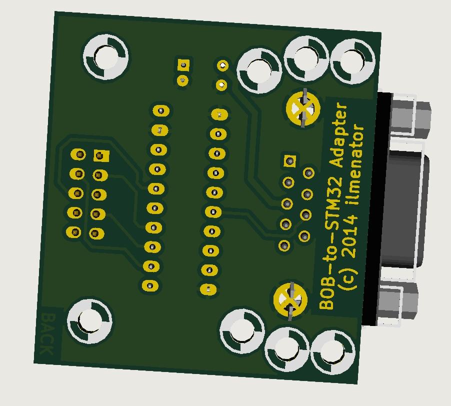
I think there is a misunderstanding here. The MIDIbox Matrix routing functionality is not running on the STM32 core, but on the FPGA. It is a stand-alone project and not a hardware extension to other projects. The STM32 core in this project only controls the routing and provides a user interface as well as program storage. So, even if you only wanted a 4-port router for this project you'd still needed the FPGA board. (In which case it would make more sense to go for a software-based router running on the STM32 core itself). If you want more MIDI ports in your other applications like NG, SEQ or whatnot, you need the IIC board. However, if you only want to spare the space for two of SmashTVs MIDI I/O boards, or if your MIDI ports should be physically away from your core board, then the BOB in combination with the above adapter board is also an option.
-
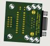
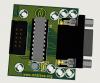
Here you go: This adapter board connects to J11E of the STM32F4 discovery board. With this in place, you can use the BOB as a regular four port MIDI I/O extension with the discovery core board.
-
I was pretty sure this would be something for you, too... :tongue: I'll get back to you once I have received the next version of the FPGA boards which will provide a means for MIDI activity monitoring on all in and out ports.