

latigid on
-
Posts
2,524 -
Joined
-
Last visited
-
Days Won
149
Content Type
Profiles
Forums
Blogs
Gallery
Everything posted by latigid on
-
© 2014 latigid on
-
© 2014 latigid on
-
Yes, I've made one
-
Très cool! Tu as utilisé un Core 8 ou 32 bit?
-
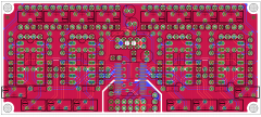
Routing everything now, a good holiday project! Question: will any application make use of J2 (serial out) for chaining multiple modules? It seems unlikely so I would prefer to remove this connector. In this case, would it be better to terminate the digital out in some way (tied high or low)?
-

AOUT NG : only half expected voltage in bipolar
latigid on replied to julienvoirin's topic in Testing/Troubleshooting
No, I have an offset wired from the +12 V buss, divided through a trimmer. The offset is mixed through an op amp summer, so load changes shouldn't be too much of an issue. This also uses a more stable inverting amplifier that needs to be inverted again for correct signal phase/polarity. The perfect place to introduce an offset voltage! -
And another one, I can't see why this couldn't be compatible with MBCV v2 either:
-
A lot to read, been away a few days! For the breakout board, please remember this:
-
AOUT NG : only half expected voltage in bipolar
latigid on replied to julienvoirin's topic in Testing/Troubleshooting
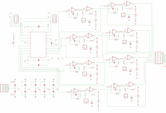
Here is a different approach: inverting amp followed by an inverting mixer/unity gain buffer with switchable +5V offset Two more op amps but probably a better design decision. A positive/negative voltage swing is often used to sweep above and below a set control e.g. an LFO modulating a filter frequency. As the new MBCV application will generate LFOs I think full scale CVs are still widely applicable. -
There was the option of more gates (at least in V3) but I think CV is limited to 8 outs. I was wondering whether you could clock a second AOUT module for another 8 channels, it's possible in theory but I'm not sure about the programming side. You could always build a second one! The analogue inputs are used as gate outputs in the current setup. There is a tap tempo function however...
-
 Whoops! This has the correct inverting amps!
 -
Thanks for the schem! I have added some filtering for the PSU (10 ohm resistors) and changed the trimming circuit. It's based on a design from http://www.bartonmusicalcircuits.com/dnq/ and uses an inverting amp stage (with additional low pass filtering, the idea of Seppoman) and a switchable offset/unity gain inverting mixer. Some connectors need changing, but this will be done in conjunction with the other board layout. If somebody with a scope could measure the frequency of any digital noise/glitches that would help me design the LPF. Should the DOUT chain perhaps be terminated to stabilise operation? EDIT: I had the op amp inputs reversed, fixed now :)
-
Possibly relevant for you: I have in mind an idea to create a Eurorack version of AOUT_NG The connection from the SEQ would be buffered/level shifted gates, () DIN sync and clock, and a buffered J19 line through a DB-25 cable. The Eurorack module would receive power from the +12/-12 V supply, powering a re-routed AOUT board. CVs would be passed to another board stacked on top containing 3.5 mm jacks.
-
I offer 4x new 6582A SID IC (to trade) for 1x sammichFM
latigid on replied to LunarLeonis's topic in Fleamarket
The original kits for sammichFM were AUD200, so 4x 6482 is quite a good deal price wise. When you say "new" what do you mean? From Wilba's sales or another NOS supplier? -
With regard to AIN, I think these are used for the gate outputs at the moment.
-
That's about it :) I have some questions if you could: How are you powering the AOUT_NG board? If it's from the Eurorack power buss do you have any issues with digital noise crossover? Do you find the DB-25 connector intrusive in any way? Thanks for stopping by!
-
http://www.analog.com/library/analogDialogue/Anniversary/2.html AD tips on gain and offset controls
-
AOUT NG : only half expected voltage in bipolar
latigid on replied to julienvoirin's topic in Testing/Troubleshooting
Bumping this topic. As I am interested in re-routing the AOUT_NG board I would like to rectify this issue at the same time. An ideal situation would have unipolar mode from 0 to 10 V and bipolar as -5 to +5 V. What can be done? Should the offset control also include a buffer stage? -
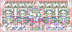
I would like to re-route the AOUT_NG board for use in Eurorack systems. I imagine two stacked boards with a final panel of 6-8 HP. The first contains PCB-mount 3.5mm sockets for CV 1-8, Gate 1-8 and DIN SYNC. I don't there's room for proper 5-pin DIN sockets. A DB-25 connector would be used to bring gates, DIN-sync and J19 from e.g. a MB-SEQ or a standalone Core for MIDIBox CV. I would think about simple emitter follower/common collector circuits to indicate "Gate On" states. LEDs could also be useful for CV indication, especially in negative mode. The second board would be a clone of the current AOUT_NG circuit (assuming that this is okay) except fitting onto a rectangular PCB. The power would come from the Eurorack buss, and would probably need extra filtering and/or optoisolation to keep digital noise out of the rails. Either sandwich-style or DIL connectors would bridge the two boards. The benefits I can see are: easier power requirements for a MB-SEQ and a more useful layout of connectors for patching as part of a modular system. I already have a DB-25 breakout board that buffers and level shifts gates inside the SEQ enclosure. Anyway, just a diving off point for further discussion. I firstly need a copy of the .sch file for the AOUT circuit, otherwise I will have to translate it from the .pdf diagram. I did try to contact Seppoman but he doesn't seem to visit here much any more.
-
Does anyone have the .sch file for AOUT_NG? I'd like to make a stacked Eurorack module with sockets on one board and the AOUT_NG on another. Tx,
-
Went to the N/O/D/E synth meeting in Lausanne yesterday. New Mutable modules look very cool!
-
Went to the cool N/O/D/E synth meeting in Lausanne yesterday. New Mutable modules look very cool!
-
http://avishowtech.com/buy
-
Also, is the computer supplied by the same wall outlet as the audio system? FWIW, I got very good results with no ground loops with my RME Fireface 800 as an expensive "soundcard". Although the converters are excellent, I wouldn't recommend going with this though. Firewire is notoriously difficult to configure, especially on PCs and even more so on laptops. There is apparently a magical TI chipset that avoids DMA conflicts but production has since moved onto different hardware. The results are very poor quality audio with many dropouts if you get it wrong. Does anyone know of a good USB3 or other interface?
-
MIDIbox FM V2.0 Prototype Front Panel Mockup 3
latigid on commented on Sauraen's gallery image in MIDIbox Gallery
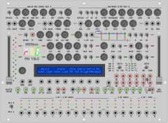 Tasty!