latigid on
-
Posts
2,524 -
Joined
-
Last visited
-
Days Won
149
Content Type
Profiles
Forums
Blogs
Gallery
Everything posted by latigid on
-
I am looking at a Mouser order right now, the PT78ST105H is obsolete, but there seems to be a pin compatible replacement with slightly better ripple characteristics and a lower input voltage (7 V, if you need it). It is # 78SR105HC which is currently being made obsolete. Mouser have under 500 units remaining so get in quick (or find another alternative)!
-
Perhaps you can test the IO transfer by connecting J19 (without the buffer board) directly to the AOUT module?
-
orange_hand, this may also be of interest to you: (would depend on your usecase)
-
Yes, I was thinking this. Perhaps it would be better to use a 15V supply, then it shouldn't have trouble with 12V.
-
Hi, I haven't routed a board before, so I would appreciate any advice! The top ground plane has been omitted for clarity. Seeing as I am using an AOUT_NG, my design has the same dimensions and mounting holes. I would stack the AOUT on top of this one with M/F standoffs. The eight analogue outs and gates are brought out to a DB-25 connector. The gates are either buffered or amplified to approximately 12V, selectable via jumpers. I am using a 100k/71.5k voltage divider for approximately 2.4x gain. At a 15V supply a 100k/50k combination would provide a gain of 3. One could also mount a variable resistor instead of the jumpers for more control. This works on paper, but I am wondering if the op amp will swing right up to its rails? There is a spare buffer for the DIN sync/start connections also. I haven't figured out libraries in Eagle yet so some of the parts aren't quite right. <<Hmm, they probably need current-limiting resistors too....>> I am not sure how to power things inside my SEQ yet. Building a linear triple output PSU looks to be the best, but I may try a switch- mode unit. In this case power would be supplied at J1 and a daisy chain output is at J15 on the right-hand side. Perhaps it isn't quite the right thing to do, but I have isolated the grounds for the AOUT and gate signals. The ground for the gates can be tied to the same ground as the AOUT signals. Lastly, I have included pins for a DC-DC converter in case the SPSU doesn't work out. The two footprints on the top left of the board are for the muRata NMV0512SC and the Recom RS-0512D. It might be wise to include an inductor-capacitor circuit which can supposedly reduce the ripple voltage down to 5 Vpp. Thanks for looking and please share your thoughts!
-
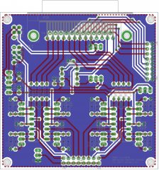
© latigid on 2013
-
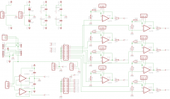
© latigid on 2013
-
Usually they will waive the shipping once you get over a certain amount. Is there anything else that you need?
-
No, I don't think it will work, unless this is an equivalent controller to the Hitachi HD44780 one.
-
Great, can't wait! :smile: One thing though: why are the "Paypal fees" different if your base currency is not Euro? You will still be paid in Euros and the currency conversion will be covered by the buyers. Others might also have currency prepaid on their accounts.
-
From Mouser there are 0.5W and 1W solutions for 10,39 and 18,26€ respectively. 70 kHz switching frequency, which I would hope to be high enough to avoid problems, but I'm not sure! The Recom unit seems to have a higher switching frequency of 100 kHz or more, so it is probably better in that regard. http://eu.mouser.com/ProductDetail/Murata-Power-Solutions/NMJ0512SC/?qs=sGAEpiMZZMtwaiKVUtQsNdN9l48nzt7a%252bz8taXcceL0%3d http://eu.mouser.com/ProductDetail/Murata-Power-Solutions/NMS0512C/?qs=sGAEpiMZZMtwaiKVUtQsNcW9zb9tavYg9JdPS%252b2oOa4%3d http://www.mouser.com/ds/2/281/kdc_nmj-19483.pdf
-
Just in case weren't finished... has anybody considered using a charge pump (i.e. a DC-DC step up converter) or similar to power the AOUT board? We're talking 20 mA max for 2x TL074.
-

Extended front panel design - what to do with two extra buttons?
latigid on replied to ilmenator's topic in MIDIbox SEQ
:) Been there myself! -
More info please, project and core type? What is the cable length and is the shift register functioning properly?
-
Hi, sorry to hijack, but your encoders are more expensive than Pollin http://www.pollin.de/shop/dt/MDY2OTU3OTk-/Bauelemente_Bauteile/Passive_Bauelemente/Potis_Trimmer_Encoder/Encoder_ALPS_EC11E15244BY.html
-
Is the optocoupler installed? With the correct polarity? "If MIDI In not working, blame this part"
-
Off to see Ander and his mothership on Saturday: http://presenceselectroniques.ch/artist/20 If you are in or around Genève I suggest that you go also!
-
Hi, are the device IDs set correctly (that is, if you are using 8-bit cores)?
-
Control surface PCB for 16 encoders/LEDrings Bulk Order
latigid on replied to Fairlightiii's topic in Bulk Orders
Picked mine up from la poste today. Who knows why, but they were routed through Zürich, thus they are well travelled (double the distance from Montpellier!). Many thanks, I hope to build something nice with them, someday. -
Do you receive quantity discounts on amounts like 100/250/1000 knobs or so? Or is the pricing fixed? Cheers for your work :)
-
Interested in a black datawheel knob for MBSEQ, I am wondering if you will get price breaks for the Waldorfs?
-
I received two SEQ windows from freddy the other day. They look great, thanks! This means there are two left for anyone who needs them.
-
Hmm, 3 mm LEDs don't fit into SEQ front panel... :(
-
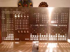 Wow, epic panel!