Search the Community
Showing results for 'STM32F4'.
-
What are the jumper settings on the 407v daughterboard? What is the position of the host/slave switch? Should be up to avoid using USB host. Sounds like it's mostly fine but you can also try other searches e.g. http://midibox.org/forums/topic/19105-stm32f4-communication-issues-with-mios-studio-no-usb-midi-available/
-

New eurorack modules from midiphy - preview
weasel commented on Hawkeye's gallery image in Members Gallery
 will do, i ordered the chip a couple days ago to try and improve on the existing unoffical driver for axoloti (stm32f4 based too), but will also try and look into direct midibox use! enough derailment, these midiphy modules look like all midibox users would ever want!!
 -
LRE 4x1 breakable RGB LED-Ring/Rotary-Encoder PCB bulk order
weasel replied to weasel's topic in Bulk Orders
Great work @FantomXR that picture looks absolutely terrific. we will evaluate the design for a couple more days and run some more tests and then finalize the bulk order with updated prices, anybody interested can PM me now. edit: fwiw, alternative method of driving ws2812 on the F7DISCO: https://stm32f4-discovery.net/2018/06/tutorial-control-ws2812b-leds-stm32/ -
LRE 4x1 breakable RGB LED-Ring/Rotary-Encoder PCB bulk order
weasel replied to weasel's topic in Bulk Orders
Wow this is amazing news, the OG just blessed us with a firmware update! I am pretty sure @FantomXR will get them running just fine now! Thanks so much @TK. this will help alot and we should get at least 2-4 LED-Ring-Boards going. I'll send you some for reference once i have the production run! I read through the mios32 ws2812 documentation and realized you need to use 48bytes per LED for the PWM DMA solution. I do understand the motivation behind this, saving CPU power, but is there a somewhat easy way to go back to other methods as described in the uC.net article you linked? Thinking of the "average" midibox tasks, i doubt it pushes an STM32f4 to it's CPU limits? Guess using the flash memory would wear it out too fast? I would love to implement it myself but that's way beyond my knowledge and time constraints, and at the same time i assume there is little need for other people to go beyong 300-400 LEDs. But how do other ie. arduino ws2812 drivers get away with just using 3 bytes per LED, on a much slower CPU? Since for 40-50 encoders i need to adress between 1500 and 1800 LED - 72kb at 48bytes, ca 5kb at classic adressing - i guess i might have to just add a little arduino or similar MCU to control the ws2812. even the smallest UNO can handle 500 ws2812 at 60Hz, and the Due with its 3-4 serial lines should be able to run all 50 encoder-LEDs i need. -

LRE 4x1 breakable RGB LED-Ring/Rotary-Encoder PCB bulk order
TK. replied to weasel's topic in Bulk Orders
Hi, STM32F4 was running out of memory - and due to an wrong linker file entry you haven't got an error after the 128k boundary of the "normal RAM" has been touched. However, this chip has some additional 64k as a so called "core coupled memory", which is located at 0x10000000 I changed the linker file and preload code to support this memory. In addition, in the MBNG application I moved the heap memory into this CCMRAM, giving us about 10k more space. Updates are available at github: https://github.com/midibox/mios32/commit/9dc48579c31766815997b0ce3eac88f9d772578a I havent't checked if this has a new negative side effect, but at least MBNG is booting and RGB LEDs are working Best Regards, Thorsten. -
These look very interesting indeed. Not as obviously/conveniently freely programmable. I am currently building a synth on the axoloti platform. While rough around the edges the patching software for it is a really great balance between simple modular patching and hardcore coding. But the hardware is kind of outdated (same STM32F4) and the community rather slow these days. There are currently notions to develope upgraded hardware on an ARM m7 or other newer platform though. http://axoloti.com/ sorry i just kind of crashed into this thread from a search result, not sure if this might have been discussed before or even is way off topic. oops.
-
I wired up my 7pin SPI 1306 according to this diagram using 1k res and 10u cap. but i'm failing to get anything out of the screen. trying to just print text through the console lcd command, or the hello world program or even the NG init message. i did set the correct LCD type in the bootloader: there's this other old thread where someone had to connect the OLEDs reset pin to some other core connectors GPIO pin iirc? is that really the way to go, no convenient simple conncetion available? i tried manually setting the reset pin to 0/3.3 via the testlcdpin command, no success. while manual, that should do the same trick as the GPIO pin reset above, right? edit: i realized the J15 reset pin is connected to the DC pin of the OLED? so no manual reset this way? i tried doing some measurements. core board soldering seems ok. power/ground voltages are also where i think they're supposed to be everywhere. is there a page or list with debugging measurement points on the STM32F4 core board? DINOUT and AINSER 64 work for what its worth. more pictures of my "circuit" i realized in the above picture the SDA cable was in p4 instead of p6, that was not the issue though. OLED supposed to work on 2.8-5.5v, i tried both 3.3 and 5v jumper settings. yeah i know my soldering is "sub par" GND and VCC from both j15 and the OLED going to the power strip on the breadboard, and the blue wire to the reset pin.
-
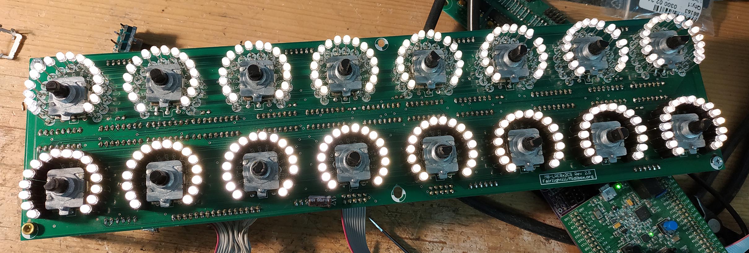
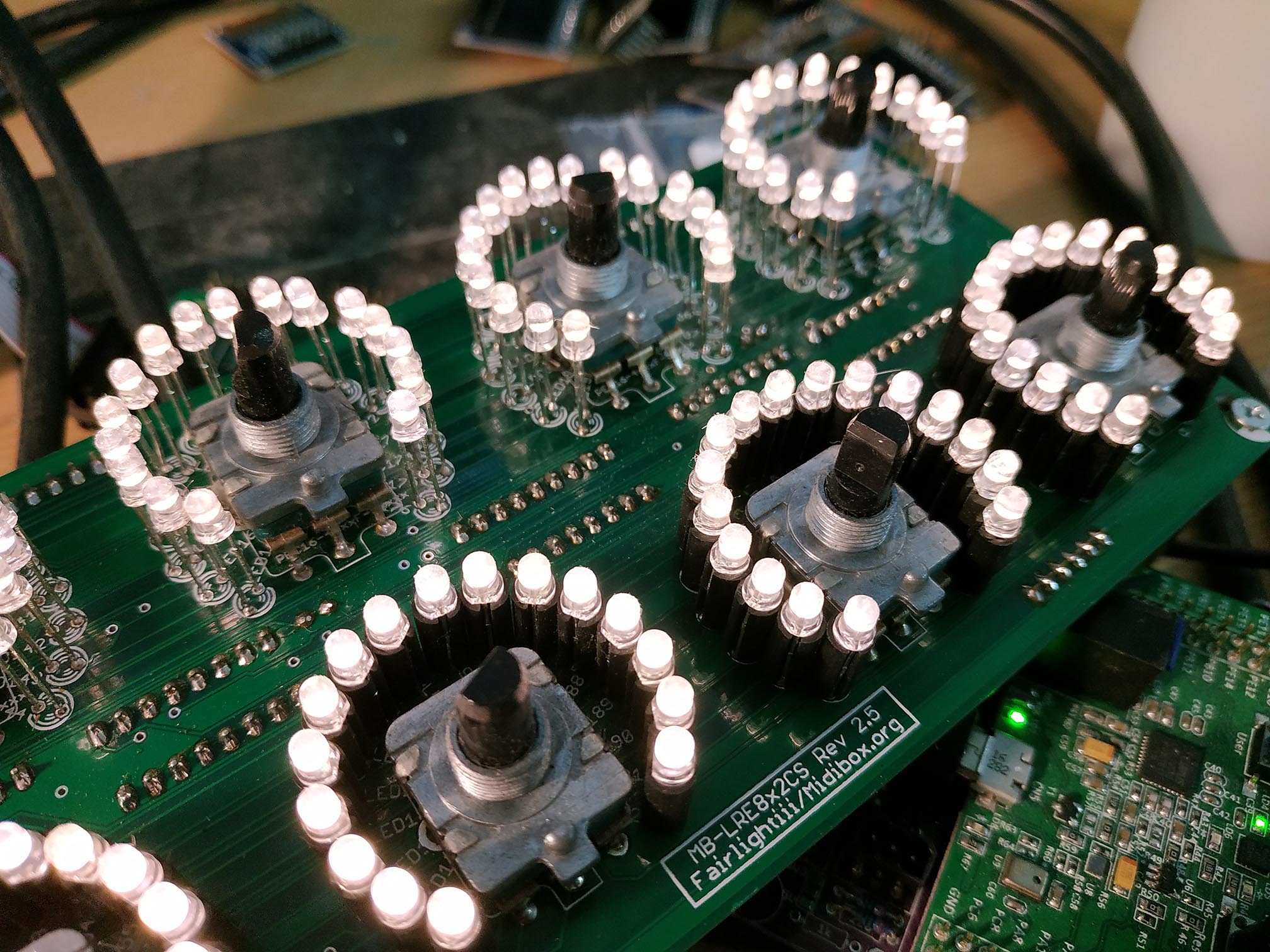
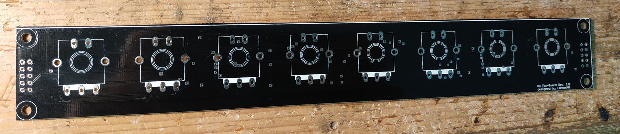
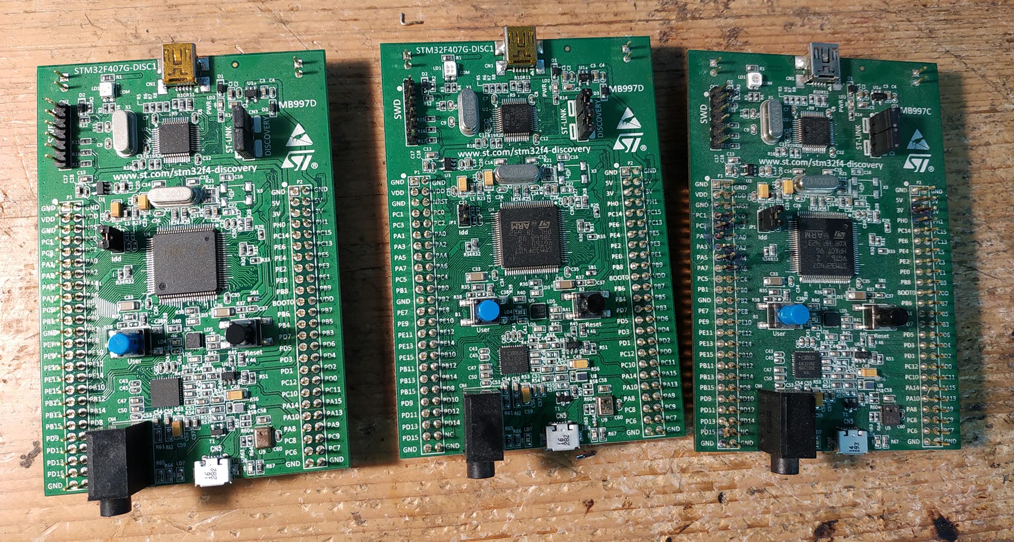
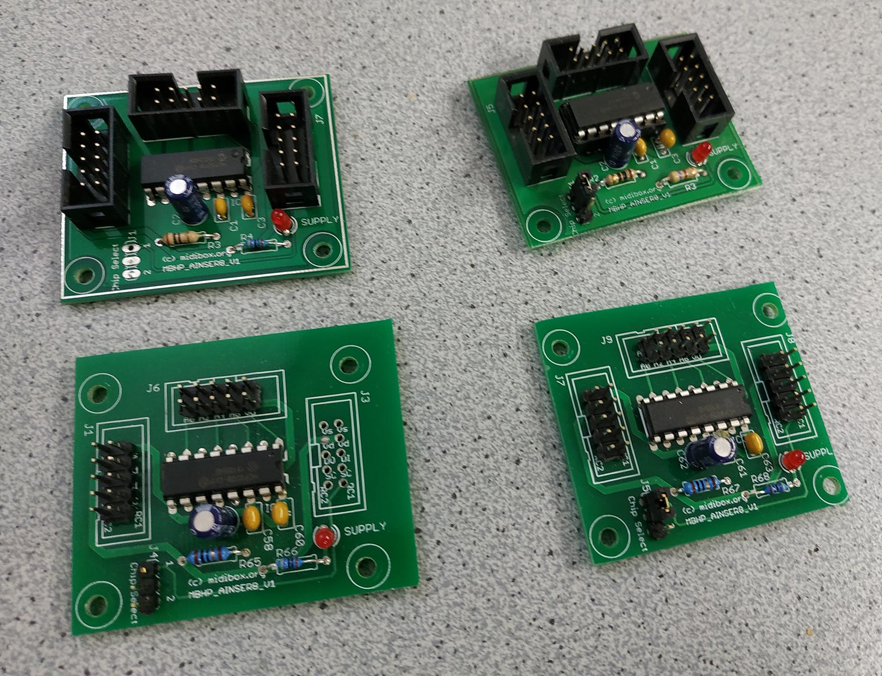
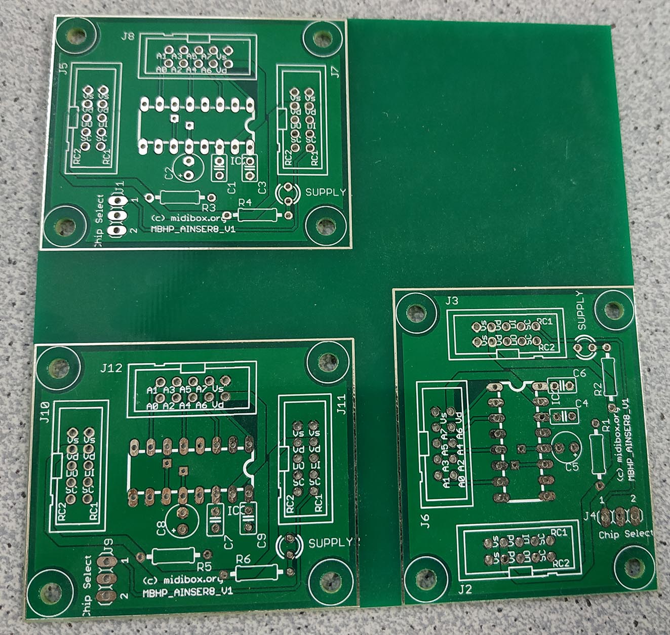
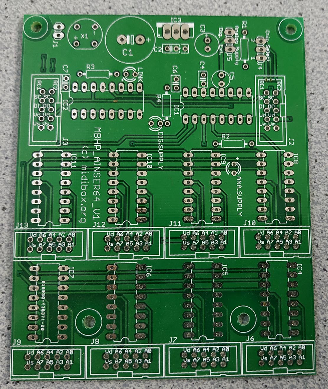
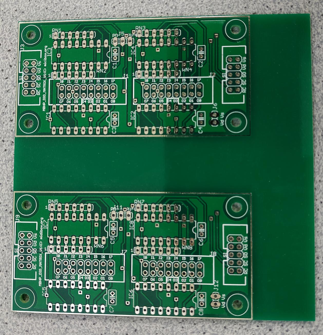
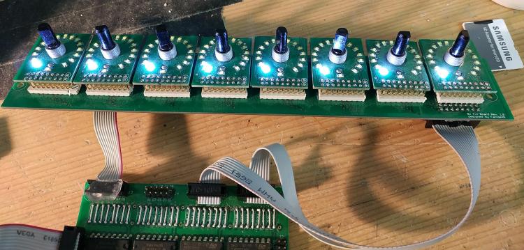
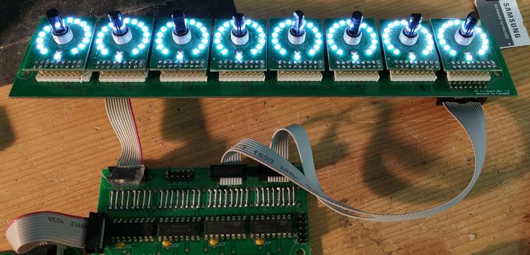
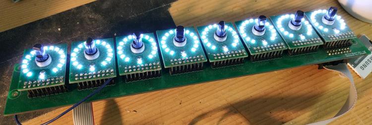
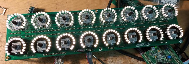
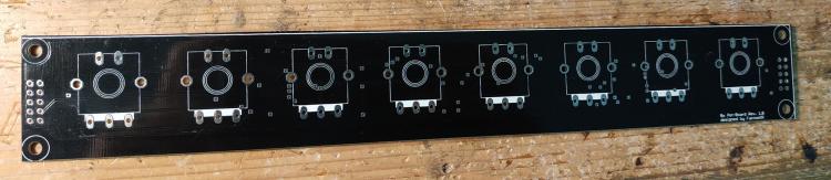
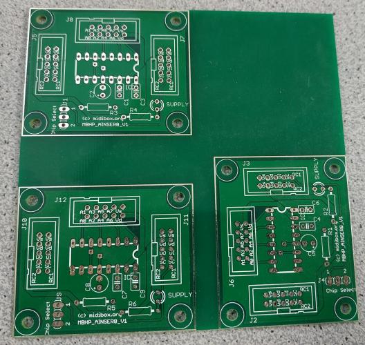
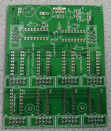
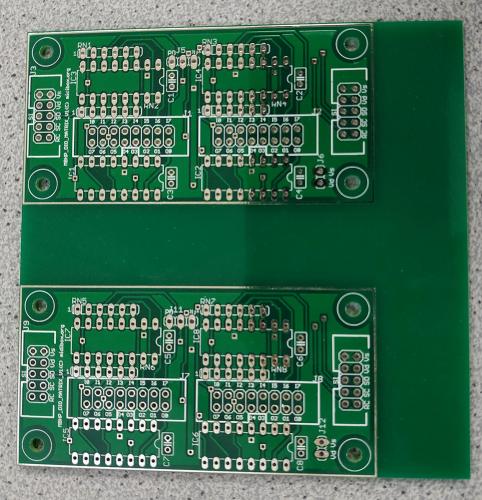
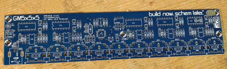
Hey people, I cleaned up my room a bit and found some PCBs I do not need anymore. Here we go: This is something I developed years ago! It has a PCB with 8 encoders with LED rings. Although they look blue, they are not. The LEDs (0603) are white! As you can see the PCB an be connected to a standard DOUT-module even without any resistors. The LEDs won't get damaged. I did a mistake in the wiring of the LEDs at this point. So if you follow the official LED-Matrix-Pattern, you will get crazy results. But anyway: This is a software-thing. If you change the matrix-pattern, they work perfectly. I'll advice you about it if you buy it. I have two of those available. On one of them I needed to fix a trace (3rd. picture on the left). But it's perfectly working. Encoders are Bourns PEC16 with integrated switch. Underneath there are three IDC connectors for the encoders and switches that can be directly connected to a DIN-module. Price: 30€ each o.b.o. Next is a LRE: It has warmwhite LEDs. Lower row is mounted on spacer, the others not. Encoders are PEC16 with integrated switches. On the switch-header I soldered a flat-cable directly. So if you don't need it you have to remove it. Price: 35€ This is PCB where you can mount encoders on the top. Necessary shiftregisters have to be mounted on the backside. It's SMD, but can be soldered with a good soldering iron without any problems. No need for SMD-equipment like reflow-oven. Price: 3€ each STM32F4 Discovery! Price: 15€ each AINSER8-module assembled. Price: 6€ each AINSER8-PCBs. Each PCB includes three layouts. I will not cut those in pieces. You have to do it by yourself. Price: 4€ each PCB (=> 3 AINSER8 Layouts) AINSER64-PCB Price: 5€ each (two available) DIO-Matrix-PCBs. Each PCB includes two layouts. I will not cut those in pieces. You have to do it by yourself. Price: 4€ each PCB (=> 2 DIO-Matrix Layouts). GM5x5x5-PCB Price: 5€ That's it for now! I'm located in Berlin, Germany. Best, Chris


-
@SimonSays R33D should be ok - please also check connectivity of all datalines - from the problematic J15 port to the waveshare board (through the headers) - some years ago, i had a display with similar garbage and one data line was disconnected. You might also want to reflow the pins of the waveshare headers (on the wCore PCB) before measurements, just to try that out before you measure a lot of pins. If it still does not work after reflowing, measurement from J15 to the waveshare core MCU and then to the STM32F4 IC pins are the only way to check for continuity (quite some work!). Also check for "neighboring" unwanted shorts, as those could well cause the problem, too. I'd recommend to reflow every pin first, especially as reflowing on R33D seems to have helped! Many greets, Peter
-
Hi Peter, Thanks for the clarification! Yes, Sauraen's project looks amazing, but unfortunately well beyond my current skills. Would it be fine then to use one of the PIC18F4685 chips that I have left over from my MB-SID build? I suppose I could save the STM32F4 module for a different project, or sell it for that matter. No big deal. Regards, Theo
-
Hi all, After having previously built an MB-6582, I thought I'd have a go at building a midibox FM. Following TK's build guide on ucapps, I've built the OPL3, DIN, DOUT, and CORE modules using PCBs ordered from Modular Addict. For the core, I thought it would be fine to use the newer STM32F4 module because it is mentioned as a more modern alternative to the PIC-based one. However, only after finding out more about it (my mistake), I'm now unsure if that was the right choice. I don't want to try to replicate Sauraen's 2.1 version because it looks far too ambitious for me and I need to rely on something fairly well documented and straightforward. My coding skills are very basic, and I just want to use the control surface of TK's 1.4 version. Is it possible to build the 1.4 version using the STM32F4 without writing or changing a lot of code myself? Or would I be better off using an LPC17 or a PIC-based core instead? I already have some spare PIC18F4685s, but I suppose if I use an LPC17 then I won't have to add a midi IO module later. Is that correct? I appreciate any advice. :-) Cheers, Theo
-
Hi, Does anyone here do track recording in Ableton Live with MB SEQ? I have problems getting it right, and wondered if anybody had any tips. Setup: MB SEQ V4 (STM32F4) MIDI through USB Lenovo Intel Core i7 / Windows 10 RME Fireface UCX Ableton Live 9 I have tried running Ableton as Master and Slave I have tried with Monitor in Ableton off and on There is always a mismatch, just within a few bars some hits can be be about 6 milliseconds early and some about 6 milliseconds late. Cheers, Hal
-
Mike's ceased his midibox business, Jörg who has the leftover stock is getting me the DIN DOUT for now but the STM32F4 is only to be had from the US right now. I have a more general question about midibox and general open source guidelines, as i am all new to this. whats is the process if were to produce midibox based boards extension boards like described above, make twice the amount of my personal need and have the other half commercially sold through the usual suspects, at cost though without any earnings for me. do i have to get approval from thorsten or anybody? i assume some kind of crediting according to whatever open source license has to happen? can someone take me by the hand here please? it's been kind of hard to get any kind of positive or encouraging response from most of the people in the midibox supply scene i spoke to so far.
-
Hi - very new to the forums and building a kit for the seq v4+, I have received some great help from Andy and Peter over on the seq v4+ troubleshooting thread but I have a more general SD card handling question. Background: I'm having a hard time getting the SD card to be 'found' so I can load a test program, and have not had success at all with that. Just keeps saying SD card not found. I've tried many variations of cards, my latest is a brand new 4GB sandisk SDHC microsd with adapter formatted FAT32. I have NG 1.036 installed and everything seems to be good so far...MIOS studio recognizes it no problem but just no SD card is found. I can confirm the cable is fine, no shorts between pins, I have continuity from card socket (a SD-RSMT-2-MQ) to the MCU board and even tried the 'simple SD card cable' from TK's website. Nothing so far has worked getting the SD card found. I'm on Win10 but same happens on Mac laptop. I think I had the cable backwards the first time on power up but I don't see how that could have fried anything, besides it still runs in MIOS studio. How does the SD card get detected in the STM32F4? Is it the mechanical switch on the side where the 'write protect' and 'card insert detection' are both tied to ground? Or is it one of the pins like CS? (I've read there are a few ways possible).CS (SD socket pin 1, J16 pin 10, RC1) is tied to GND. Is that right? Is there any type of way to 'fake' SD card detected because maybe it can read/write it ok but thinks it's not in there? Or perhaps a MIOS studio diagnostic? I see there is some commands via the 'help' command but not sure if any apply to SD card testing. I appreciate any insight anyone has into this, Thank you!
-
I have yes, and I found some really cool projects. It's really crazy the stuff people come up with and build! Now, I haven't found any examples with an LCD touch screen interface, so I took a good look at the MIDIbox NG board and yeah, I guess that is going to be difficult. Parallel/RGB won't be possible just because of the lack of pins available. It probably would work via SPI/I2C but that seriously limits the choice in displays. Any ideas on how to do that are always welcome. And thank you for your link! Took quit a bit of reading through the MIOS code to get my head around it and find out how I would write my own code for it. But the link you provided already made things a lot clearer. Anyway, overall I think MIDIbox is really great. Already ordered the STM32F4 board while I'm checking out all the modules ;)
-
Hi, for the past few weeks I have been looking at development boards as a base for developing audio/music projects. I almost decided on an STM32F7 discovery board until I found out about the MIDIbox NG. This board with its STM32F4 module looks ideal for what I want to do but I have two major questions before I can decide. I'm currently trying to learn as much as I can about MIOS and trying to find related threads on this forum but in the mean time all the help would be greatly appreciated, thanks! 1) Can I use a capacitive touch screen with the MIDIbox NG ? The projects I want to develop will make use of capacitive touch displays from 4.3” up to 7”. Either directly driven from the board or by using an intelligent display like those based on FTDI's EVE or Nextion. But I can't find any example of this, which makes me wonder if it is possible at all ? Would this mean I should write my own driver for MIOS for the screen, or could I use existing drivers and STM32 libraries for this, or even integrate GUI frameworks like µGFX, touchGFX or embedded wizard, etc .. with MIOS ? And how difficult would that be ? Or is MIOS not really designed for this and should I better look into MPU/Linux based solutions? 2) From what I understand so far, MIOS is mainly a MIDI control/processing OS, but how suited is it as a base to develop your own synth for instance? Are there any limitations or can you basically do anything you could do on a barebone STM32 board and thus use all its code examples, libraries, dev tools, toolchain ,etc ? I guess what I'm asking is, how well does MIOS and it's amazing features integrate with your own code or can you only use API functions? How transparent is it and does it impose limitations ? Are there currently projects like these (synths, Eurorack modules, etc ..) that are based on MIDIbox that I could check out to get an idea what is possible? (I've been looking at the MIDIbox gallery and there are some truly extraordinary devices, but most seem to be controllers and I haven't yet found anything with a touch GUI) Thanks!
-
 After the stm32F4 core was made available, and there finally was some fine fpd files, BLM, TPD etc I decided to upgrade my Seqv4 in the style of beutyofdecay_ However, after upgrading to STM, finally getting application running and setting up HW file with the one for BLM then TPD as a beginning, Im having problems with the wilba panel. BLM seems to work as intented, as well as TPD, but Wilba does not correspond properly to the functions when I press the buttons, utility and others are moved, choosing tracks show several leds lit, etc Has there been another version of the CS panel since 2009ish? Mine is the blue 2009 version. Its the same result with every version of the wilba basic configuration. Its the same behaviour even without BLM and TPD connected. Attached is the HW file. At startup buttons Track group 1 and 2 and track 1, track+parameter layer 1, edit, mute, pattern and forward light up green. And as said, even though buttons will light up when pressed, the functions do not correspond to panel/expected. Panel was working fine on LPC17 core. MBSEQ_HW.V4
 -
I agree! I have been thinking of experimenting with a tracker software and transition my midibox to a midibox cv v2 to take advantage of the modulation capabilities. After reading all of this topic, I found a hex file finally. TK's repos can not be downloaded, so I probably need to copy all the files one by one for the most recent version. Apart from the hex file, all we need to do is to connect AOUT_NG the same way as SEQ v4 to the stm32f4 board and come up with a SCS wiring, then we are all set for using cv v2 right? Can we use it with Wilba's CS? I think this is a very good project and I haven't seen anything DIY close to it. Did this project fade away?
-
Hey people, I try to understand how the DIN is even working in the STM32F4-Core. PB14 is not going through the HCT541 buffer. It goes directly into the IC. If I understood it correctly the purpose of the HCT541 is to do a level-amplification. It takes the level from the STMs outputs (which is 3.3V - 0.4V for HIGH for CMOS or 2.4V or TTL) and amplifies them. As the HC165 and HC595 are powered from +5V they need 3.15V to see a HIGH-signal. As the HCT541 delivers 4.5V for HIGH the HC595 does of perfectly work. But why do the HC165 even work? As I said it doesn't get an amplification. So in theory the HC165 sees 2.9V for HIGH but that's not enough so it should stay LOW and doesn't work. But it does... Can someone explain this behavior? Thanks, Chris
-

Who knows how to implement a USB Stack for PIC microcontroller?
Ravager replied to Ravager's topic in Design Concepts
if it was just that easy. You also need to charge your pads so a simple ADC might not do the trick. One very hacky solution: What's the input capacitance of the STM32F4 ADC channels. Can they be clamped to high or low internally? Can the tiny charge on the ADC input be transferred to a pad through a multiplexer or will all of the charge be eaten up by leakage currents? I guess it's safer to use hardware which is intended for this. But maybe there is a workaround? -

Who knows how to implement a USB Stack for PIC microcontroller?
Antichambre replied to Ravager's topic in Design Concepts
And a single CPU, an STM32F4 to take advantage from the MIOS32, AND good ADC with multiplexed input? An 8 inputs ADC with eight (8:1) multiplexers will give you 64 inputs ;) -
dipCoreF4 and dipBoardF4, a compact Core.
Antichambre replied to Antichambre's topic in Design Concepts
In this extended chart you can see the functions available for each pin, (It's from stm32f4 documentation.) -
Hello I'm talking about AOUT_NG http://www.midibox.org/dokuwiki/aout_ng#the_pcb Have a search in the forum, someone do the test times ago and it work (MB_NG) You have to chain the TLV at DOUT pin and enable 32CV at .ngc file configuration (supposed you run MB_NG on a stm32F4) Best Zam
-
CORE_STM32F4 Module, LCD, and fire
Wapata replied to Wapata's topic in MIDIbox Documentation Project
Thank you both of you ! In fact I'm an old newbie here. My core was made in 2016 (edit: the metadata of my pictures says October 2017), and I follow uCApps for more years than that ! Maybe 2004 (... Wow.. so long ?..). It's okay for me to broke an LCD, but the point here is about the indication on the website, they are confusing about the ports of the STM32F4. I mean... Really. But on the other hand, I should have double checked the vcc and ground for sure. -
Hi! Using a MIDIbox Hardware Platform, CORE_STM32F4 Module do change the latency that prevent using MidiboxNG instead of MidiboxKb ? I'm currently doing the keyboard but... There is no "octave up/down" buttons to wire on the MidiKB project. So I need a second STM32F4 with MidiboxNG to do that (and other things). Will this slow down the latency ? What is the best way to link the two STM32F4 (to have only one USB cable to the computer) ? Usb via USB host ? Midi ? An other way ? Other question: how do YOU use the midi router of MidiboxKb ? I think it's cool to make old midi stuff converted to USB but I may miss something. Please tell me if I not clear !