Search the Community
Showing results for 'STM32F4'.
-
Hi Here, I would like to know if it is possible to flash the mios Bootloader and mios applications on other cards than STM32F4-DISCO, for exemple on this boards : https://github.com/mcauser/MCUDEV_DEVEBOX_F407VGT6 I would like to know how it would be difficult to make Mios studio working with newer stm32 board like Teensy 4.0 or Stm32H743 board like https://github.com/mcauser/MCUDEV_DEVEBOX_H7XX_M Thanks for all, Best
-

LoopA V2 Introduction, Features & Support Thread
Hawkeye replied to Hawkeye's topic in MIDIbox User Projects
@latigid on thanks for the trace picture - and good idea about inspecting the waveshare! Good point to mention the crystal and cap removal and the necessary changes to the top headers there! @Altitude I'd also recommend checking, if the connection from PA11/PA12 to the STM32F4 MCU on the waveshare board itself might be interrupted for some reason, e.g. some dodgy soldering on the daughterboard header top on the PA11/PA12 pins by Waveshare :). To check with a DMM, you could visually trace these two pins back to the STM32F4 and measure directly from the MCU pin to R30/R31 on the LoopA Core, to see if there is connectivity. Just tried this, the traces are nicely visible on the Waveshare PCB and with a loupe/magnifier you can relatively easily see where PA11/12 go to the STM32F4, then you'd just need a fine multimeter probe tip to check where those two USB signal lines are interrupted on their way to R30/R31 on the core. If there is MCU connectivity to R30/R31, a last check would be to test the USB socket itself, i've never had a fault there, but there's always Murphy's Law :). I've also just compared pictures of your soldering with high-res video tutorial images of the board - can't really see a difference - i think it looks all good. Many greets, Peter -

LoopA V2 Introduction, Features & Support Thread
Altitude replied to Hawkeye's topic in MIDIbox User Projects
>..Before you desoldered the Waveshare daughterboard, i would have guessed the STM32F4 might have been a dud, maybe bad flash memory... But if it starts up and boots the app when powered by mini USB, that's clearly working. And as you said, it must be some connection to the USB port... I thought that too so I swapped the STM chips and it behaved the same way so it wasnt the chip. That was further proven when I took the core off and that worked by iteself. Its something on the mainboard thats hanging it up.. >did you have the onboard Waveshare power switch moved from "USB" to "5V In", when it was installed in the LoopA core? yes. now that the core is off I'll trace back to the USB socket when I get some time. Either its something stupid that I missed (likely) or some weird edge case issue (unlikely) -
LoopA V2 Introduction, Features & Support Thread
Hawkeye replied to Hawkeye's topic in MIDIbox User Projects
@Altitude Thanks for the good quality pictures - soldering really is super clean! Will compare your pictures this evening with a working core PCB and report back if i see some differences. Before you desoldered the Waveshare daughterboard, i would have guessed the STM32F4 might have been a dud, maybe bad flash memory... But if it starts up and boots the app when powered by mini USB, that's clearly working. And as you said, it must be some connection to the USB port... Question that was probably asked before: did you have the onboard Waveshare power switch moved from "USB" to "5V In", when it was installed in the LoopA core? That's the only thing that could explain it, i think - if that switch was not moved to 5V, the Waveshare board wouldn't get proper power and would not start up when powered by external LoopA Core USB. Two red small power LEDs should be lit on the Waveshare board when all is well. You made sure of that probably, but to be sure just wanted to mention it anyways :). If it's a hardware defect on the LoopA core or the Waveshare, we're glad to send you replacements of course, but it would be great to trace it and find the problem - thanks again for the tests and your patience! @latigid on: could we try to trace the USB signal pins from the STM32F4 microprocessor right to the USB port on the LoopA core? Which connections would need to be tested? Best regards, Peter -
 So at one point during my development of an app on NG basis on a STM32F4 core, my SesEx tool stopped working. I used it to send messages to both a Mackie C4 and a Korg M3R, which both responded in the beginning. The confusing thing is, that I can still communicate with both via my .ngc and .ngl scripts. I address them both by their ports (Macke on MIDI port 1 = 1000100000001000; M3R on MIDI port 2 = 0100010000000000) and there it works! Still something must have been misconfigured on the way and I can't imagine what, because I'm still pretty much in the beginning. I also used to get SysEx dumps form the M3R on request, which also stopped working..
 -
Hi Florian, this sounds very good for me and meets exactly my original imagination! It fully fits to my plan and you mentioned one thing that is important: you used the same board STM32F4 for both -- the NG as well as the KB software. Out of the KB threads I assumed for a long time that it can only be realized with the LPC17 board and somehow there were some inconistencies in Thorsten's documentation that confused me. I also had a look on your github page that finally convinced me that I'm on the right track! Now I can sleep much better again and proceed with the mechanical work... Thanks & and best regards to Toulouse (I was there last time 20 years ago for business -- you have nice restaurants over there, for instance the Caves de la Marechale ), Andreas
-
Hi Famtom, thanks for the feedback! I was not aware of it. I have the STM32F4 Board already in place, so I guess the only chance to change to more than 16 velocity values is to change it somewhere in the NG software. Or is there any physical limitation for the 16 values instead of the 128 that can't be changed in the software? I didn't dig deep into the software yet... Right now I'm taking care about the mechanics, and as soon as this is done I'll take care about the software and electronics. My original goal was just to use what I have in place, and this is the TP/40WOOD and the STM32F407 board. Both I already got years ago, but didn't have the time to build a real master keyboard out of it. And now I have the time to build -- since my retirement approaches... Or do I really need the LPC17 core for the KB instead of the STM32F4? Thanks, Andreas
-
LoopA V2 Introduction, Features & Support Thread
Hawkeye replied to Hawkeye's topic in MIDIbox User Projects
@momelq thanks Robert, that all makes sense - i'll notify you when there is a prerelease version with the temporary piano effect available for testing :). The STM32F4 is a quite powerful MCU and there are still resources left - the sequencer engine eats not up that many cpu cycles, the rest is used as a low-priority background task for the display refreshes. So, if we add a CPU-hungry subroutine on a clip, the worst that would happen first is that the screen refresh rate goes down a bit - but of course, it all depends on how complex the algorithm would be. We've also got a bit of RAM to spare (depends a bit on the resolution of the CC storage). If you want to describe the algorithm (via email is also possible), i'd be all ears, but can't promise anything! :) No temporary sustain FX then, it's probably really not necessary or could even be manually activated with separate sustain pedals of the connected synths. Have a nice evening and best regards! Peter -
Hi Florian,, I have now nearly the same project in front of me: Generating -- out of a naked TP40WOOD from Fatar that I got some years ago -- a MIDI Keyboard like the Doepfer LMK4+. Doepfer charges 1500€ for this, and the solution with MIDIbox is much, much cheaper, thanks to Thorsten! I'll use the STM32F4 on a MIDIbox NG baseboard plus DIO_Matrix plus MIDI_IO plus AINSER8 (for the wheels and Pots) plus a 2x40 LCD blue plus a MBHP_DIN for the 24 Keys. So the same functions as the LMK4+ and a very similar control panel. But much cheaper. Will see how it works... Next phase is the Mechanics for the whole thing, and then the Electronics and the SW. May be I'll contact you at a later stage if I have questions. Especially the SW development might be a pitfall... Cheers, Andreas
-
So I am planning to build a microcontroller as an interface between a Mackie C4 Pro and, theoretically, any kind of Hardware/Software component. The component that is to be controlled will be determined, and the configurations specified, by templates which will be stored on an SD card. To realize this I will be using the STM32F4 module with the SD card interface and a MIDI 2x2 module. Eventually another 2x2 is planned to additionally connect a MIDI keyboard. I am a newbie to the MIDIbox forum so I started researching and decided to take the NG project as a starting point. To me this means that in order to implement this I need to alter the .ngc .ngl and .ngr files to a) have a communication with the Mackie that will, basically, always stay the same and b) generically prepare the other side of the microcontroller so that the user can specify the mappings to his hardware/software himself. RPN, NRPN and SysEx must be possible. This of course means that the chosen parameters and their state will be required to be displayed on the Mackie's displays, which, after reading the NG and STM32F4 specifications, I think is possible. A final requirement is that the configurations will have to be stored into a textfile (I was thinking XML) so that the user won't need to actually open the .ngc files and do his settings there, but rather that on startup the device considers the textfile as belonging to a certain configuration file, checks if something was altered in the textfile, if so applies it to the configuration data and then sets that up as the current configuration state. What do you guys think? Does that sound possible? Did I choose the right components? And has anyone ever done something similar and encountered problems that maybe I could encounter too?
-
Hi ! im trying to build a cheap cdj-styled usb-mp3-player with a raspberry and i went into trouble with the midi-messages from my STM32F4-Core Midibox. I got some pitchfaders, buttons and encoders which i want to use to test walmartone MIXXX(a DJ-SW)-performance. On my windows-machine everything works like a charm with Traktor. I receive the messages with the amidi -p hw:1,0,0 -d command. hw:1,0,0 is the adress of the midibox. For the pitchfaders (midipitch-message) i receive 3 bytes as desired. I use the SendPitchBend-Command for that. For Buttons (MIOS32_Send_CC) i receive lots of junk with the right message at the end: F0 00 00 7E 32 00 0D 40 42 75 74 74 6F 6E 20 38 20 67 65 64 72 75 65 63 6B 74 00 F7 BE 08 7F It should be (Channel 15 CC 08 Value 0x7F) For encoders (MIOS32_Send_CC too) there are also lots of junk bytes in the message: BE 1E 7F F0 00 00 7E 32 00 0D 40 45 6E 63 6F 64 65 72 20 30 3A 20 31 00 F7 In this case the right Message is at the beginning: (Channel 15 CC 30 Value 0x7F) How to get rid of that junkbytes? MIXXX works fine on the pitchfaders but it cant read the buttons and encoders. I already tried to compile my app without MIOS32_USB_MIDI_USE_AC_INTERFACE 1 as i need that setting for windows but there was still the junkbytes in it. Anyone experiend something like this on Linux? How to get rid of these junkbytes? For me the junkbytes doesnt make any sense. But they are always the same at the specific buttons and encoders....
-
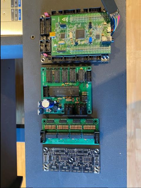
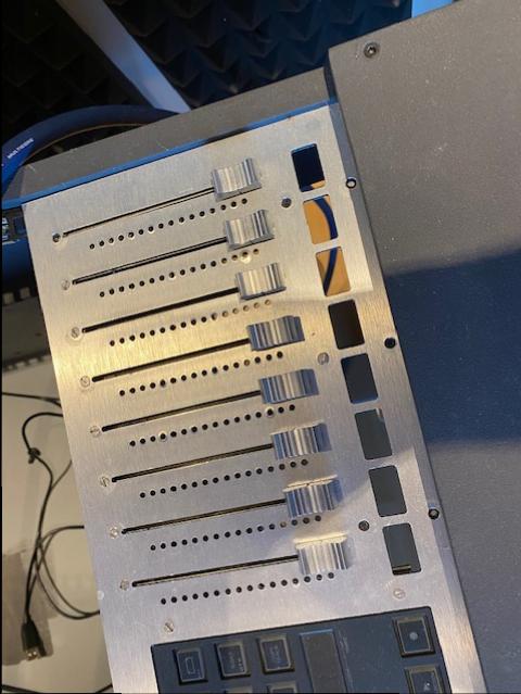
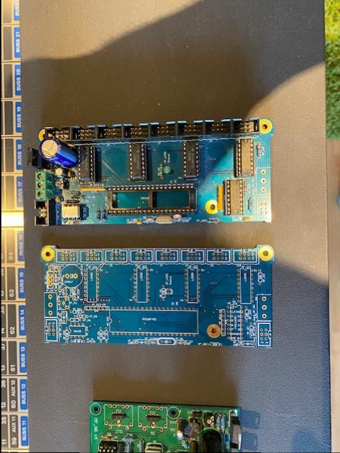
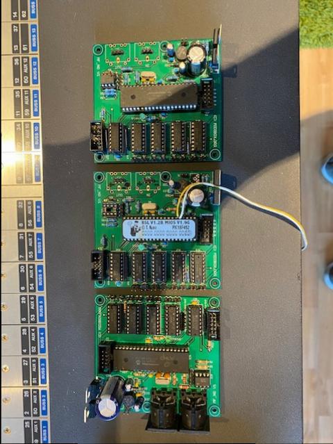
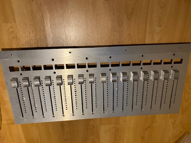
Hello all, After a long time with practically no time to continue my project I have decided to downscale my project. That's why I'm selling a lot of stuff: 1x STM32F4 Core Module Board+ STM32F407G-DISC Assambled, tested and working (no sd card), use at own risk 1x MF_NG Module + PIC Assembled, tested and working, use at own risk 3x MF_NG Module + PIC Assembled (1 board missing 1 IC), not tested 1x Custom MF_NG Module (no PIC) Partly assembled, not tested 1x Custom MF_NG Module (no PIC) Not assembled 1x DOUT Module Assembled, tested and working, use at own risk 1x MIDI IO Not assembled 26x 100mm Alps Motor N fader (some o-lead, some normal lead) Unused, only mounted, no caps 2x 19 inch frontfpanel from dibond (aluminium, plastic, aluminium) 1 with cutouts for 16 faders, OLEDs and led VU meters 1 with cutouts for 8 faders, OLEDs and led VU meters and 2 Steinberg CMC cutouts Preferably selling it as one lot, but I might consider selling individual items. (I might keep de STM32F4, but not sure, defends on the offer) Make me an offer. Shipping costs for buyer.


-
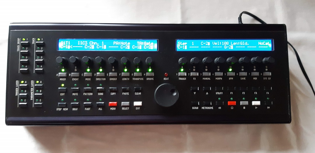
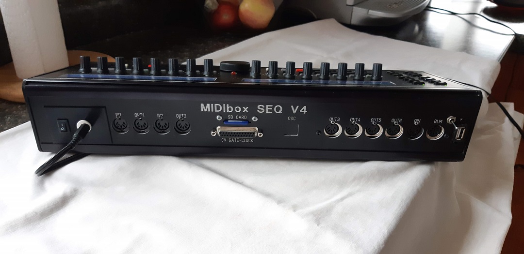
Seq V4 for sale $600 usd. Midibox SeqV4. in great condition. STM32F4 core. It has 2 IN, 6 midi OUT and 4 midi IN & OUT on the USB (when used on a Mac). It has the OTG mod, a USB type A port to hook up controllers in host mode. Updating can still be done by switching to device mode. Modified power section to accomodate the updated core. Ultimate dawless!.


-
- 1
-

-
Hi, I im trying to run simple character lcd, without core module, but keep getting some random chars, or even just blocks, but it keeps blinking. I followed schematic from uCApps page for STM32F4, but the part to set Luminance i dropped and simply connected it to ground, Could be this a problem ? Tried to connect from scratch everything a few times, but still getting the same error... Please, if anyone has a tip what could be the problem, mine is that as i am lame at electronics, somewhere is connection problem maybe, im bit confused about the resistor array. Here is a video showing the behavior of LCD https://drive.google.com/open?id=1CPgCp6t-rewshbGq7Yprdonu_htadADo Thanks, Martin
-
Hi Karg, I tried switching the voltage toggle to all positions on the STM32F4 but it doesn't resolve the problem. It is on 5v in. Followed the video tutorial to prepare the core. The displays appear to be 3,3v on the Midiphy shop. How can I proceed further? Thanks!
-

MIOS32_BOARD_Jx_PinGet (x) returns 0 (when set 2 ANalog)
Phatline replied to Phatline's topic in MIOS programming (C)
Can anyone confirm that this simple code Work/not Work? j5pinget.zipj5pinget.zipj5pinget.zip anyone with a STM32F4 can test this.... the code should not hang your device since it is only call every second. thx 4 help. #include <mios32.h> #include <FreeRTOS.h> #include <task.h> #include "app.h" // Init J5A+B Pin 0 as ANalog Input void APP_Init(void){ MIOS32_BOARD_J5_PinInit(0, MIOS32_BOARD_PIN_MODE_ANALOG); MIOS32_BOARD_J5_PinInit(4, MIOS32_BOARD_PIN_MODE_ANALOG); } void APP_Background(void) {} // Get J5A-B Pin 0 every second void APP_Tick(void){ static int seccount = 0; // init counter seccount++; if (seccount > 1000) { seccount = 0; // reset counter static s16 state = 0; // Get J5A0 state = MIOS32_BOARD_J5_PinGet (0); MIOS32_MIDI_SendDebugMessage("J5A-Pin0: %d ", state ) ; // Get J5b0 state = MIOS32_BOARD_J5_PinGet (4); MIOS32_MIDI_SendDebugMessage("J5B-Pin0: %d ", state ) ; } } void APP_MIDI_NotifyPackage(mios32_midi_port_t port, mios32_midi_package_t midi_package){} void APP_SRIO_ServicePrepare(void){} void APP_SRIO_ServiceFinish(void){} void APP_DIN_NotifyToggle(u32 pin, u32 pin_value) {} void APP_ENC_NotifyChange(u32 encoder, s32 incrementer){} j5pinget.zip -
Do you mean the original STM32F1 based core: http://ucapps.de/mbhp_core_stm32.html or the more recent STM32F4 based core? Compare: http://ucapps.de/mbhp_core_stm32f4.html I maybe have one of the STM32F1 boards, not stuffed, available. I can only confirm on Friday this week as I'm travelling....
-
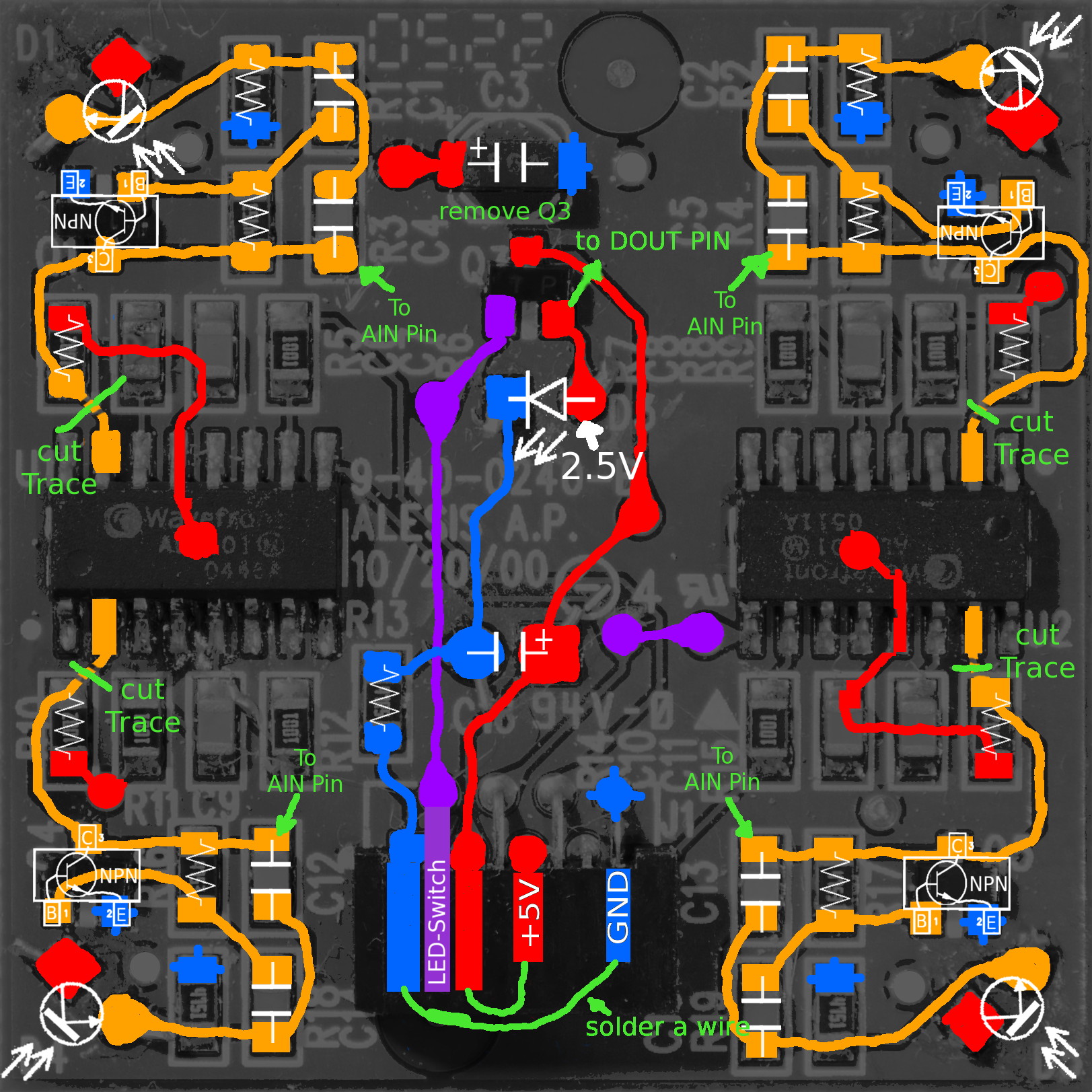
XYZ-IR-Dome Controller (alesis photonX)
Phatline replied to Phatline's topic in MIDIbox User Projects
i try now to mod it this way... going directly with analog signals to STM32F4:
-
How about https://www.midiphy.com/en/shop-details/138/2/wcore-pcb-and-usb-pcb-midibox-diy-do-it-yourself-solder-midi-microcontroller-stm32f4 ?
-
TK about mixed CLCD/GLCD: maybe it is already implemented, the actual bootloader says: [2781.832] help [2781.832] Welcome to Bootloader 1.018! [2781.832] Following commands are available: [2781.832] set fastboot <1 or 0>: if 1, the initial bootloader wait phase will be skipped (current: 1) [2781.832] set single_usb <1 or 0>: if 1, USB will only be initialized for a single port (current: 1) [2781.832] set spi_midi <1 or 0>: if 1, SPI MIDI interface will be enabled (current: 0) [2781.833] set enforce_usb_device <1 or 0>: if 1, USB device mode will be enforced (current: 0) [2781.833] set device_id <value>: sets MIOS32 Device ID to given value (current: 0 resp. 0x00) [2781.833] set usb_name <name>: sets USB device name (current: 'Proton') [2781.833] set lcd_type <value>: sets LCD type ID (current: 0x00 - CLCD) [2781.833] set lcd_num_x <value>: sets number of LCD devices (X direction, current: 2) [2781.834] set lcd_num_y <value>: sets number of LCD devices (Y direction, current: 1) [2781.835] set lcd_width <value>: sets width of a single LCD (current: 128) [2781.835] set lcd_height <value>: sets height of a single LCD (current: 64) [2781.835] lcd_types: lists all known LCD types [2781.835] testlcdpin: type this command to get further informations about this testmode. [2781.835] store: stores the changed settings in flash (and updates all LCDs) [2781.835] restore: restores previous settings from flash [2781.835] reset: resets the MIDIbox (!) [2781.835] help: this page [2823.093] lcd_types [2823.094] List of known LCD types: [2823.094] 0x00: CLCD [2823.094] 0x01: CLCD_DOG [2823.094] 0x80: GLCD_CUSTOM [2823.094] 0x81: GLCD_KS0108 [2823.094] 0x82: GLCD_KS0108_INVCS [2823.094] 0x83: GLCD_DOG [2823.094] 0x84: GLCD_SSD1306 [2823.094] 0x85: GLCD_SSD1306_ROTATED [2823.095] 0x86: GLCD_SED1520 [2823.095] You can change a LCD type with 'set lcd_type <value>' [2823.095] Please note that newer types could have been integrated after this application has been released! lcd_type will set all Displays to the same Type (i think) i want to mix one 2x40 CLCD with 2 GLCD (SSD1206) on a STM32F4 core where to start? i bet i have to use "GLCD_CUSTOM", and have to write a custom driver - which i actually dont know how to. but maybe someone has already. thx 4 help
-
Hello, Did you ever manage to resolve your sd card issue? I'm have the exact issue on the same hardware. I tried building the additional cable as well, and even tried removing the pcb and connecting the "simple SD card cable" directly to the STM32F4, and still getting SD card not found issue. MIOS studio connects to the STM32F4 without any problems, but the SD card doesn't seem to work. Anyone have any suggestions? Thanks!
-
Hi Andy, Thank you very much, for the moment, my aim is to roll my own pcbs, so i can keep things tidy in a quite small enclosure. But first, i'll try to breadboard something in the next few days. (unfortunately a miswiring seems to have killed my STM32F4-DISCO right now) Cheers, Thomas
-
Hi Thomas Let me know if you want a PCB to drive multiple displays: http://wiki.midibox.org/doku.php?id=display_driver current version at least fixed the mirrored J15 connector. The connector for shift registers is J10B for STM32F4 Cores. Best, Andy
-
It's available now. Works only with STM32F4 - in the SCS AOUT page, scroll a bit right so that you see the "Cali Offs Disp" items. Display should be set to "Bip." Change "Cali" to -5V, an offset will appear. This one can be increased up to 4095 Following "Cali" points are -4V, -3V, -2V, .. 5V - offsets can be changed between -2048 and 2047 While changing the offsets, use a multimeter to check the result until value is matching. Best Regards, Thorsten.
-
Great work Thorsten !! Side question, is it possible to hook ESP32 and STM32F4 cores with direct midi/UART connection (high speed without opto like I do between 3 STM core here) And use it as a RTPM wifi bridge ? Best Zam