Leaderboard


Popular Content
Showing content with the highest reputation since 10/22/2009 in Image Comments
-
 A W E S O ME ! Just discovered that. Wow!2 points
 -
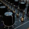
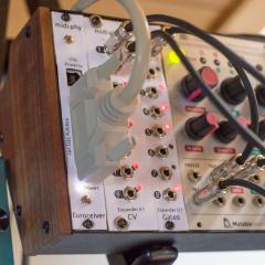
 MBHP-compatible-MidiIO - Module for Eurorack, + Thru Ports.. + Jumpers to switch between 3,5 A-B Standard.... ++++ you can use it to internaly wire, or to Frontpanel wire... so there is a solder jumper to select which LEDs are lighting... I for me will use it upside down - so when you look at the rack, you see 4 LEDs, and the midiwireing is inside the rack...1 point
 -
 Oooh, it looks so high-tech!1 point
 -
 https://codereview.stackexchange.com/questions/136406/tetris-in-c-in-200-lines ;)1 point
 -
I need this in my life and studio. Can it play Conway’s game of Life as a screensaver?1 point
-
Can it run doom?1 point
-
Looking Great!1 point
-
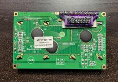 This little pin converter from @Altitudereally cleans up and simplifies the character LCD wiring.1 point
 -
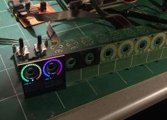
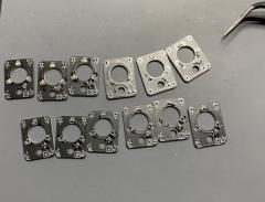 Love these encoder backlight PCBs by @d0pefish1 point
 -
 I know I’m commenting on a 3yr old thread here, but there’s clearly something special about building the MB6582. I’m actually on my 3rd now and somehow, I still can’t get enough?1 point
 -
 Beautiful1 point
 -
Amazing photos Peter! Thanks also to Adrian for the awesome case work.1 point
-
Looks great, congrats! :)1 point
-
 That is a thing of beauty.1 point
 -
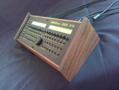
 yeah picture is too small i want some details of this beauty! great job! building a hardware controller for one specific plugin is very intriguing and reminds me of this guy, great projects: http://www.synth-project.de/diva.html1 point
 -
Is this a midibox? What is the point when most of the parameters are already accessible on the synth? This makes sense on a Juno alpha for exemple but a 106 !? >understood! It's for the virtual one The picture is too small but anyway if you did this your-self... Well done! :) BR Bruno1 point
-
 I have the line driver board, not yet installed, to drive a 16x4 BLM that's still in construction. It's definitely an interesting option for the future. Still wrapping my head around the SEQ4... what a beast hahah. Great work!1 point
 -
 OC is VERY similar to yarns but those are all 4 channel devices.. The way I went about it it was just like this thing: https://github.com/westlicht/performer-hardware/blob/master/sequencer.pdf 8 channel 16 bit DAC (DAC8568) and same output stage as Yarns using the internal reference of the DAC (Not the power rails like AOUT, yarns uses an external reference also). I started working on the board but other things got in the way and its on hold. It was a small modular type device that was supposed to be plugged into the back of my 10hp breakout1 point
 -
 What a beauty! Looking forward for the kits.1 point
 -
 Hi, Peter! Saw your 2 hour MIDIbox SEQ building tutorial at Youtube, great work!!1 point
 -
@Antichambre This an old project, but I'm still not finished the control surface. Enclosure has taken from old soviet "MICRO" calculator Elektronika MK-44 but it has no main PCB, so I'm still searching for another one to take keyboard from it for more authentic look Rio asked me for the project files, so I've uploaded everything to public. Yes, design is based on Olivier's original Shruthi-1 CEM filter board, other parts is quite standard except OLED - CORE8 PCB with MidiboxSID v2.042, Stereo SID6581 PCB and AOUT_NG. PSU is taken from old DVD player - +5/+12/-12 volts, CEM VCF powered with +12/-12V. The only one noisy part is OLED's boost converter, I was thinking of powering it directly from +12V rail, should fix the problem.1 point
-
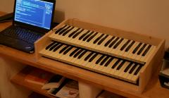 I always like your wood style too!1 point
 -
 Can you share yourvpot pcb1 point
 -
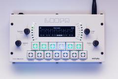
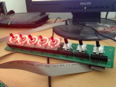
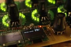
 Cool display tricks! Could consider "SAVE" instead of "STOR"?1 point
 -
 It's awesome!1 point
 -
 Very nice Alfredo! Congratuwelldone :)1 point
 -
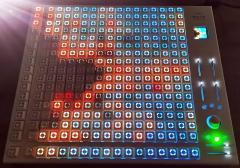
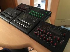
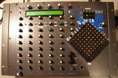
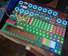 Oh, all three front panels have used row drivers; in MIDIbox ASIDITY it was a bunch of TO220 NMOSFETS, in MIDIbox FM V2.0 / V2.1 it was a Darlington array, and in this one it's eight TO92 NMOSFETS, they're right next to the orange LEDs in teh middle. Obviously the shift register pins can't sink >1 amp! But I don't quite understand the issue--MIDIboxes have been using BLMs with this scheme for 15 years. And in fact, since only one row is on at a time, having 8 or 16 rows from each pin of the shift register is just the same as having each shift register pin drive one single LED by itself. That's what the DOUT module is specifically designed for. You're right about PWM, but I don't use dimming on any of these panels. :) I don't find that it's terribly useful to convey information to the user.1 point
 -
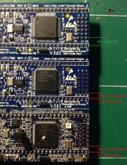 Hi! It's possible to bend the pin to make them match the MBHP PCB, that's what I did. But I think it's better if you can get a rev B! You can find some pictures of my bending here : http://midibox.org/forums/topic/18552-lpc1769-rev-c-different-layout-than-rev-ab/?page=2#comment-1671611 point
 -
 Heavyweight B)1 point
 -
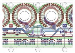
Great stuff! Lovely routing :)1 point
-
 Great work, I really hope there will be a way to get our hands on these. I'd love a few strips of this!1 point
 -
Oh yeah, looks so good !1 point
-
Wow, looks amazing!1 point
-
 wow. thats stunning!1 point
 -
 me wants1 point
 -
Darn, it looks so pretty :wink:1 point
-
 Awesome!!! Whats it all do? Did you install a sequencer? I had one of these and they ar built like a tank... Post an audio link...1 point
 -
 Yarr! This is shaping up to be a really nice MIDI controller!1 point
 -
 Very classy looking unit!1 point
 -
 Cool MB6582! Great to see it working! Many greetings, Peter1 point
 -
 absolutely hot!1 point
 -
LOVELY PIECE OF WORK!! :D1 point
-
 Yeah man! That's real perfoboard hardcore!1 point
 -
 Hehe hawk! Please turn it around so we can see the security code too :D. mmmmmmmmmmmm. moar midiboxes for technobreath - free even :D1 point
 -
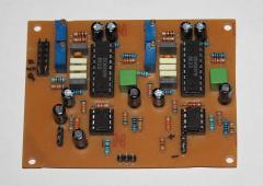
 Thanks! While this module lacks the unique synthesis qualities of the original Polivoks, much of the sound essence is captured by the raw filter :) Great with SIDs! :)1 point
 -
Thanks J, i am beginning to understand, why they love this filter in the Shrutis :)1 point
-
The mighty Polivoks makes everything sound better1 point
-
 Congrats! It is always nice to see a fully populated MB6582 :)1 point
 -
 I just got some very funny looks when I declared "Oh, that's sexy as hell" in the office.1 point