

ilmenator
-
Posts
2,305 -
Joined
-
Last visited
-
Days Won
37
Content Type
Profiles
Forums
Blogs
Gallery
Everything posted by ilmenator
-
OSHPark is great indeed, they have top notch quality PCBs. However, if you need larger size boards OSHpark can become quite expensive. Also note that shipping is only free within the US. However, for small boards their service can't be beaten. Psykhaze has already given a good overview on the rest of the pack from China mainly. For PCB design I would always recommend KICAD, which is free, open, and has turned into an amazing piece of software in the last two years. Before, I have worked with Target and with Eagle, both manufacturers that try to lure you with crippleware, i.e. the free versions are seriously limited, either in pad count or in board size. As latigid on mentioned, all these tools have rather steep learning curves, so in my opinion it just doesn't make sense to invest time into learning a software, only to eventually discover that you need more features later on. Because then you either have to spend the money or start learning again... There are also lots of tutorials available for KICAD as well.
-
Looking good. For the TPD, be aware that this will require some smd soldering - however, this is not a big deal, the parts are reasonably easy to solder anyway. Just make sure you follow the instructions in the Wiki.
-
That's brilliant!!
-
Are you sure you got the numbering right? All my Kicad libraries (also for Molex parts, though I don't have this exact part number) start counting pin numbers from the left when the tab is at the bottom, so your pin 3 would be my pin 1!?
-
From experience (my own and many other TPD users) I can say that what we have now is close enough .
-
Well you have a point in that. The 2-pin connector has the exact same purpose as on the original TPD, it disconnects the encoder switch. Can you send me a link to the Molex connector you are using?
-
Decoupling caps are highly overrated. If really paranoid you could still fly a through-hole capacitor across the IC... You need a SEQ somewhere anyway, so power will be taken from there. Adding a power supply connector just creates false hopes, I think. I am not sure about a TPD in a Eurorack either, but there was a request so I checked what I could come up with. Personally, I will try to avoid the moneypit Eurorack.
-
I am not exactly sure what you are talking about? You want to obtain the same results using some non-TPD??
-
I think if you want a wider frontpanel you could also stick with the original PCB? I am not sure when it will be available to the general public, it might take another two months or so.
-
A number of people claimed interest in a Eurorack variant of my TPD, so I sat down and tried to modify the parts layout to somewhat better accommodate the Eurorack width. Here is a screenshot of the PCB. It is essentially built on altitude's advice on Eurorack dimensions, which I know nothing about... is this 14HP? So, the PCB is 100mm x 69mm (height x width), and the parts list is identical to the regular standard TPD. Also, the UI has the exact same layout, so you can use the template in the Wiki for your front panel. The mounting holes are different, though. Depending on interest, I might get a run of boards made after an initial testing of the prototype which will probably go to altitude.
-
A number of people claimed interest in a Eurorack variant of my TPD, so I sat down and tried to modify the parts layout to somewhat better accommodate the Eurorack width. Here is a screenshot of the PCB.
-
-
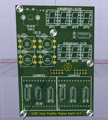
From the album: EuroTPD v1.0
A screenshot of the newly created EuroTPD, a Track Position Display board better suited for Eurorack systems. It seems there was some interest in this. -
Did I just hear TPD?
-
pm sent...
-
Do you have the schematics for these cartridges? If so, the layout should not be a major problem.
-
Man, I wish I had some more time again for these things...
-
Yes indeed - currently boxed, but I do have a small collection of EMU samplers... no software sounds like an EMU. Have you converted these waveforms to EMU proprietary samples already?
-
Tell me something about the EMU 6400 mod, please!
-
Yes exactly, I didn't see any such display board, hence my suggestion.
-
Good to see this happen! I think it would be great to have the encoders much closer to the displays - in my opinion this is crucial for ease of handling and for keeping the overview in live situations. Which would obviously require a different kind of modularity: e.g. modules/boards that hold all the functionality required for 1 or 2 displays with associated encoders. That way, there would be true scalabilty in the system.
-
-
It is actually the other way round. Noise issues apart, there is another reason to go for variant B instead of variant A: assuming that you want to achieve a "tight" layout that requires as little board real estate as possible, it is never a good idea to have parallel traces on the front and the back side, because you have nowhere to cross these traces. Usually, it's a smart move to dedicate the front side of the PCB to say horizontal traces, whereas the back side will then mainly hold the vertical traces. This approach helps to avoid vias and reduces the amount of headache you will have once the layout gets a little more complicated (i.e. you are using more than a few components).
-
I was obviously referring to MIDIbox group on Facebook .
-
I am not surprised. What should it be good for? It's great to have a single forum here, with all info either on ucapps.de or in the Wiki.
-
Perfect, thank you very much!
