Leaderboard


Popular Content
Showing content with the highest reputation since 12/05/2019 in all areas
-
Necro bump, here are some more hi-res pictures, as the ones over at MI forum are just thumbnails.5 points
-
Here is mine :) Only heard about this project last week and now I'm the owner of this beautiful beast. Thanks Peter and Andy for all the help (me spamming you) in the last few days :)4 points
-
Got mine going -- many, many thanks to Michael Menze for building it.4 points
-
I read a lot of guides. Successfully compiled ASM code. The OLED display works well with an 8bit driver. If anyone needs the firmware, here is: setup_sammich_sid_8bit.hex3 points
-
Hello dear midiboxers, I just wanted to share the new EP that I just released, called "La couleur préférée du carrossier": https://kevingotkovsky.bandcamp.com Four library-digital-bossanova-world tracks entirely sequenced with the one and only SEQ V4+ ;) If you like 70's and 80's type sounds, you might enjoy this! Cheers, please don't hesitate to give me any feedback, KG3 points
-
This is it! I finished my one. What a great device! Needs some patience, but very satisfying to see, how it grows. Many thanks to all who made this possible! Great job! regards, roland3 points
-
Hi all, I just joined to post the pic of my finished unit. Some comments from my side if someone starts building one and reads this before ;) - Pay good attention to the video instructions about the parts and part numbers. Always double-check the right manufacturer part number in the BOM, as some are very similar, but have totally different functionality. - If you accidently mix up the resistor network ICs and realise it too late, you can also use a chep "non-industrial" heat-gun to unsolder them, one which is not for soldering only, but e.g. for heating up and forming plastic stuff. (i use mine mainly to ignite my charcoal for BBQ ;). I checked my user manual to see what temperature setting on the heatgun (1-9 or something) is approximately which temperature, i set it to about 320-350°C. Worked fine for me, jus make sure not to force the IC off to early, wait until the solder is liquid again. The resistor network itself is not very head sensitive, be sure to disassemble or cover everything else around it that might get damaged (i removed the pushbotton caps again). - Do not forget to set the 3V jumper for the OLEDs in the beginning, you have to disassemble a lot if you are almost finished ;) Test your OLEDs as early as possible. - I mixed up some of the different pinheaders of the mouser BOM, ended up having not the long ones left to connect the two PCBs. Then i used some different ones i had left (i think from Reichelt) and they worked even better as i did not have to push them down again as Peter did in his video. - A little bit longer cable from the JA board (on the left-hand version only?) to the next board would have been helpful, the fitting and assembly was very tight, several times the connector went out of the socket. Ok, now i have to connect all my stuff to get going again. This was a lot of fun, and regarding the complexity of the project the drawbacks were minimal and easy to fix. Thank you all for this awesome work! Have a good time, Enginerd3 points
-
Here is another Midibox in the wild. Lacking both time and skills to really build one myself, i had one of the trusted builder to handle that part for me. This one was built by @Menzman (Michael Menze) here on the forum. Very nice chap and highly recommended if anyone else wanna take this route to get your hands on this wonderful piece of hardware. You can find him via the trusted builders list @ midiphy) edit: if a moderator can move this to the correct thread in the forum (v4+) it would be great, i just saw i accidently put it in the wrong one :) sorry! @Hawkeye ?3 points
-
Hi All, Here you can see all the necessary boards to build the HAARP. Best regards Bruno3 points
-
i pulled them by hand. is there a special tool? the picture does not match the actual impression. one can clearly distinguish which steps are selected.3 points
-
Hello some update were made on the dokuwiki ;) dipCoreF4 A reduced Core for your MIDIbox App, an STM32F405RG in a DIP40 format. Features MIOS32 uses same processor family and drivers(no deep change). Same internal hardware as Disco or wCore (speed, memory, peripherals, etc…) . Board pinout and package compatible with a MIOS8 PIC USB connector onboard. 2 OTG are available, second(new) USB is Host only. 5V power input and led. 3.3V regulator and led on board. 74HCT541 on board for the 5V output ports. User and Reset buttons. 2 user leds. 12 extra pins for USB, buttons and leds. Your favorite Core is now a current component easy to integrate. All commons MIOS32 ports are available except: General purpose J10x ports were removed. LCD port was reduced to a serial one, no more pins J15.D0-D7 , no back-light power supply. 2 UART only(2 MIDI In/2Out). 2 AIN channels only(e.g. pedal inputs). SPI slave only supported by J19(SPI3). Check the dipBoardF4 for more details Download dipCoreF4 eagle lib for easy integration in your design. dipcoref4_v2a.zip Pinout The dipCoreF4 and the legacy MIOS32 ports. Check dipBoardF4 for more details about the connectors. BOM Due to the small SMD, which is sometime a difficulty to solder, the board is already assembled by manufacturer, except the connectors. The mini-USB is optional. Qty Value Package Parts Mouser Reichelt Conrad LCSC Notes Headers 3 1*20 male 437-3501012000006101 No Adapted to sockets Mill-Max 0552-1-15-01-11-27-10-0 or 0553-1-15-15-11-27-10-0 Connnector 1 mini-USB THT USB 571-1734510-1 no! for other ref take care about restricted area!3 points
-
Another successful build. Thanks to all involved for such a great design and realization of this sequencer. I followed the build videos and that kept me on track. The only problem I had was of my own doing, mixing up the resistor networks then getting erratic output on the first seq_l test. Hot air and swapping the resistor networks around fixed this. Thanks to @Antichambre for those great looking keycaps too. Looking forward to more great things from the Midibox team. Edit: I did have the odd inversion of colors on the beat LED, I had red on measure green on beat, a change of values in the config file HWCFG fixed that.3 points
-
Wood Side Story. ;) Tomorrow is sanding time...3 points
-
Number 23, I believe. More about the build soon.3 points
-
Hello friends. I am Rolf and I would like to share my latest DIY project "Jeannie" with you. It is an 8 voices polyphonic synthesizer based on a Teensy 4.1 board. I started doing it last summer. Now I have built an effects circuit for the synthesizer. "Jeannie" DIY Synthesizer Effect circuit Video The Fx menu in the synth is almost ready. The new one is still missing Display of the parameter values after a program change. There are more videos on my youtube channel: https://www.youtube.com/channel/UCXQSpP0qn5MXSkyDo6PZ4Cw Greetings from germany. Rolf2 points
-
2 points
-
2 points
-
I built my MB-6582 last year, so relatively recently... In the process I pieced together a few handy references that helped me with my build... Good luck with yours... Planning the cost of a build, based on various component options: PCB Sets are still available here: https://modularaddict.com/shop-by-brand/midibox-ucapps-de Nice pre-made Aluminum panel sets available here: http://thebeast.co.uk/?product_cat=midibox As a bargain basement alternative to aluminum, you could have panels fabricated as if they were PCBs, which saves a ton: If real SIDs are too difficult to find and/or too expensive, take a look at the best clone options: How to program your Microcontrollers: ...Or just buy some pre-programmed chips: Where to get the "Just Right" power switch: Which SID filter capacitors to use: A useful voltage testing guide: There are many power supply options available, but this one is by far the easiest: THE definitive guide for making the control surface: A nice little PCB that simplifies Char LCD Wiring: A useful way to join the boards together: Optional Encoder Backlighting:2 points
-
Unit has been finished this morning, and cheers from Berlin! Would love to get a serial, even though i missed #422 points
-
A quick video demo, made by a friend. I just gave it to him like that, without much explanation. The user manual is still not ready (blame me) but he managed to catch the thing even though he only used a few of the features.2 points
-
For anyone that's been considering the ARMSID or ARM2SID, but didn't want the headache of having to maintain a working C64 to configure them, the guys at Retrocomp have come up with a novel solution for you... It's basically a DIY Arduino shield that enables you manage the whole configuration process through a simple terminal Source code available here: https://github.com/nobomi/Arduino-ARMSID-configurator Partial kits available here: https://retrocomp.cz/produkt?id=67 I don't know about the rest of you, but for me, the SID Clone wars are over and the clear winner is ARMSID. 1. The sound is very close to the real deal, in either 6581 and 8580 mode. IMHO, it's even better than the SwinSID Ultimate (listen to examples above in this thread) 2. The design is by far the cleanest and sleekest, all the way through to packaging, delivery, quality documentation, vendor support, etc. 3. The size and form-factor are very close to a real SID, so it will fit anywhere a SID does, unlike some of the clunkier clones 4. It's jumper-less and auto-detects the correct SID emulation mode, depending on the input voltage It receives. The mode can be overridden however, using the aforementioned config editor (imagine an 8580 in a Breadbin or a 6581 in a C64c / G). 5. The price for an ARMSID is absolutely reasonable and you can save a few $$ if you need dual SID pairs, by going with the ARM2SID 6. It provides support for analog paddles if you happen to have a real C64 And NO, I am in no way affiliated with Retrocomp or the ARMSID, but I just think these guys have done a terrific job on this... Kudos...2 points
-
The 1st draft in 3D The board is roughly the size of a laboratory card in euro format (160 x 100). The Fx module is simply plugged onto the back. The current prototype Greetings from germany. Rolf2 points
-
Hello, it is quite different. If you use ARM2SID with the second SID2 socket, connect it with provided 6 pin wire, and configure it to SOCKET configuration (it is by default) it behaves in 2 SID sockets as 2 SIDs. No doubling the output, ARM2SID has enough processing power so it can process 3 SIDs inside, so in 2 SOCKET configuration it processes both SIDs (the chip select and R/W is brought to the main chip by the wire) and sends the second SID audio back to the SID2 socket by another wire. Thus ARM2SID in socket configuration with SID2 socket and the 6pin wire behaves exactly as 2 ARMSIDs. You can set in configuration one as 8580 and the other one as 6581 or adjust filters and digifix independently. The option on picture that dwestbury published above with directly connected wires is for implementing ARM2SID to C64 or similar and when you provide all the addressing by wires, it does not need any stereo adapter and it supports stereo or 3SID or FM emulation, but it needs the additional wires for addressing. With the 2 SOCKET configuration, it can work only as a stereo, not dual mono as jjonas says. The second SID2 socket provides input and output for the 2nd SID emulation, even it is an empty socket conversion placeholder. Best regards Martin Lukasek ARMSID technical suppot2 points
-
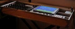
@latigid on Thanks, Andy... belatedly, here it is, the centre-piece of the studio! It may be a record in terms of slowness to post... :) @HawkeyeThanks, Peter - same to you!2 points
-
Hi! It's not the subject here, but I can explain a few quickly. Phatline is right, the M16 is a 16x16 midi I/O interface, the plan is to build a expandable router using the MCAN bus to interconnect multiple couple of Core32+M16. Nx(16x16) I/O, 16x16, 32x32, 48x48 etc... The project is called "BANDMASTER", The two prototypes I've made are working... I will come back on this project once the HAARP is finished.2 points
-
Congratulations on your hard work everyone involved! Nice to see a MIDIbox device finally get the recognition it deserves! I just wanted to update the thread and say that I had the intermittent booting issue since I built my LoopA and since installing those 2 resistors Andy suggested, it has been flawless! Such a fun little device to get ideas down quickly while remaining inspired and in the moment! One of the most important things for my workflow!2 points
-
Hi all, I think it has been requested before but I'm not sure... I would really like to divide the clock outputs more. Now the clock can get really fast, 384 ppq, and that's great! but the lowest clock is 1 ppq. And that's still quite fast. I would like to use a clock to reset something every 64th step. But for that I have to divide the clock output through an external clock divider. It would be great to get it from the sequencer itself. Now I use a dedicated track for that but I still have 6 unused clock outputs....I hope it's possible. Cheers!2 points
-
Hi there! I just completed a build of the MB6582, and during construction I designed a small PCB to neatly hold some backlight LEDs for the rotary encoders. The PCB source files and installation details are all available here on my GitHub page, licensed under Creative Commons so that anyone is free to order their own or change it: https://github.com/dwhinham/encoder-backlight-pcb I have about 9 spare sets of 15 PCBs if anyone would like some. Shoutout to @Hawkeye for the inspiration and excellent control surface construction guide! I've got more pictures and a video of my MB6582 over on Twitter if you'd like to see: https://twitter.com/_d0pefish_/status/1295104812678291465 Cheers!2 points
-
Has anyone thought to implement a drum trigger grid indication on the TPD? It is a natural fit with its 8 x 16 LED display . I know you can hold the instrument mode button down and see all the different tracks triggering but to have a visual grid might be really nice. My first drum machine was TR707 and the grid view lcd was nice!!! ~steve2 points
-
I finally got a chance to build and integrate these awesome encoder backlighting PCBs. With such a clever and functional design from @d0pefish, I had no excuses! The one impediment for me was having to learn some basic SMD soldering, but @Hawkeye's videos on the subject made it much easier ;-) I'm currently powering the lights with a 9v source, but I think this makes them a bit too bright and they illuminate the whole bottom half of the control surface.2 points
-
Hi All! Here the fabulous work from @AdrianH. The 2 casing prototypes he sent to me for checking. In black and rainbow. Some more pictures in the album Best regards Bruno2 points
-
Finished mine today. What an amazing project. I'm really impressed about the quality of this kit. I've been building and soldering stuff for many years (MOTM, Oakley and more) but the quality and attention to detail is unmatched. The tolerances alone are amazing (how the buttons fit into the case openings, the displays, the screw positions on the boards and case... the solid back plates etc. It's been mentioned somewhere on this forum already: beveled tips for your soldering iron do wonders! I admit I was terrified about SMT soldering. Turns out I really, really like it; in fact, I like it more than soldering through hole - how weird. Thank you so very much for doing this guys! Greetings from California2 points
-
Thanks for the feedback and ideas! We know there is a bit of LED stray light going on. Some people like it as it reminds them of their backlit mechanical keyboards. But for indicator LEDs it can be suboptimal. For the smaller 2x3x4/2x5x7 LEDs, a good technique we found was to use a piece of heatshrink tube. It's a great idea to roughen the top too if that is preferred. Sometimes you can also make the LED cloudy e.g. with acetone (nail polish remover) but needs to be tested. For blocking the light from adjacent Matias switches, we have another solution in the pipeline (more info soon)2 points
-
Exciting moment...replaced the SwinSID with two original SID's... and it worked! nothing "fake" anymore...great little synth !2 points
-
My best idea is to use the MUTE button to alternate between TRACKS MUTE and LAYERS MUTE pages. When you click MUTE for first time(when previous page is something else than a MUTE page) you will enter in TRACKs MUTE page: OLEDs and 1st row show the TRACKs MUTE, 2nd row shows the TRACK SELection directly, instead of the redundant TRACKs MUTE, TRACK Sel and MUTE leds lit to indicates MUTE for TRACKs Clicking a second time the MUTE button switches to the LAYERs MUTE page: OLEDs and 1st row show the LAYERs MUTE, Instruments for a drum track, parameters for all others, 2nd row still shows the TRACK SELection, or the TRACKs MUTE. in live it's interesting to have the mutes for the 16 tracks and 16 percussions at the same time, this can be an option to choose. MUTE led still lit, but now INSTruments or PARAMeters led lit depending on the Selected Track type(Drum or other), it indicates we are in the LAYERs MUTE and which type of layer it is. Option34/34: For Layers Mute Page Direct tracks butt are: Track Selection for a non drum track, layer button lit: for a drum track, instrument button lit: Option34/34: For Layers Mute Page Direct tracks butt are: Track Mute Now second row indicates the Track mute instead of the Track Selection: Clicking another time on MUTE button switches back to TRACKs MUTE page etc... Clicking other button than MUTE leave the MUTE pages. And EXIT button can be used to come back to previous page if this last was memorized on first MUTE click. Best regards Bruno2 points
-
Have completed this build. What a great project - the new case and overall integration is truly excellent! Major props to all the folks here who put this system together, Hawkeye, latigid on, thanks to Antichambre for the custom keycaps - and of course TK for creating the MB world.2 points
-
Mouser 517-929834-07-36-RK is one of the longest "standard" headers but only single row. Check the datasheet on the Mouser page and you will find other parts. None of the longer dual-row header 929710 are stocked apparently. But you could use a pair of single-row strips, which is what we do for the LoopA.2 points
-
Just been updating my website a bit with some words and pictures about various making projects... maybe this will be inspiration? I only really started soldering things in late 2016, so totally possible to do this thing :) (you can teach an old dog new tricks it turns out) http://www.robotriddims.com/makingmusing/2020/5/20/mb6582-midibox-sid-synth2 points
-
that's the bit that's confused, each chip is 3 voice mono - so pairs are used to create stereo. I think it's unlikely you'll get two SID chips that sound identical no matter if they're from the same day in the same factory really, they were a bit variable to begin with and they're now 30-40 years old. 8580s are apparently a lot less varied than the 6581s though...... As long as they're in the same ballpark the differences just tend to make them sound wider (and pretty great). I don't think worrying about which year/factory they were produced in is too important (and will be difficult now anyway as the supply of them is not great!) Having said that I did try to pair mine based on the dates on them, so I get the inclination to do so!2 points
-
Endlich! https://www.amazona.de/test-midiphy-midibox-seq-v4-diy-sequencer/2 points
-
Serial number installed2 points
-
And I also finished my build2 points
-
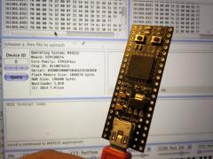
From the album: dipCoreF4
And it works :)2 points -
To me, the JB Weld bit is way tougher than the electronics ;-) Keeping fingers crossed that I don't make an absolute mess of it... -Darrell2 points
-
setup_mb6582.hex you must upload via Midi and MIOS Studio You also don't need Mblab, you just need the Programmer for the Bootloader https://youtu.be/3EkNUa2nSDE Links in the description. Bootloader http://ucapps.de/mios_studio.html http://ucapps.de/mios_download.html2 points
-
Just got it cut on my CNC and it looks like I got everything right. Still need to work on the I/O panel. I will get the DXF up as soon as I get it cleaned up.2 points
-
I have confirmed that the matrix labeling is correct with another user. I might change a few things on the rear panel, not sure how much space I have to work in my ideas may design a separate break out box. Would like to have more I/O for the filter Input and a active mixer for all the channels. Maybe get buffers for the in and out? The feedback hack is cool so would like to keep it. Here is the final panel that I am going to go with. I will post up the DXF and a gurber version when I make sure it all fits.2 points
-
Thanks for looking but in the end I cut a piece of clear plastic to size and glued it on the back of the panel. End effect is pretty much as good as the window anyway. Finished result:2 points
-
Not sure if this will help anyone but I recently made this mod to my mb6582 which worked brilliantly and is in my opinion the best option for powering the machine. I already had the switching vreg from back when altitude created the original post (thanks!). I had a couple of options for getting the 12v supply into the machine: 1. Put a c64 male power plug onto the end of a wall wart. This restricted me to a single (untested) supply that had to have the plug cut off and would create difficulties if I ever sold the machine, particularly over seas. 2. Put a barrel jack into the mb6582. Best option, but seemed too difficult given the mounting options and panel cutout is for the full size c64 jack. In the end I went with a third simple option and created an adaptor to convert any general wall wart into a usable supply. Pics included. I ended up using a wall wart from a Western Digital external drive to power the mb6582. This was an easy solution and cheap to make, and required no additional mods to the mb6582 or panel. The risk of course is someone plugging in a real c64 supply without the adaptor but no one will ever use it but me anyway. If I ever pass it on it'll come with a warning to always use the adaptor with a centre pin +ve 12v 1.5+a supply. Not sure what the effect would be if a c64 supply was plugged in directly but it may even be harmless. The adaptor only requires the +/- female barrel jack to be wired to the correct pins on the c64 male jack. Easy enough to figure out. I can't remember the exact pins off the top of my head but it'll be obvious when completing the mod. Get the plugs as close together as possible and heat shrink the lot and you're done. Cheers, Arkay. Wall wart female plug: To c64 male plug: bit of heat shrink completes the adaptor:2 points
-
Hi Hal, Probably we/someone should write a wiki entry or something on the new features! The idea is something like this: The encoders underneath the OLED displays work just as before The encoder switch functions are in theory freely assignable but are typically used to accelerate encoder data The first row of illuminated "Soft" keyswitches are equivalent to the GP buttons plus the dual-colour step LEDs of the Wilba version The second "Selection Row" keyswitches change function depending on the button lit up around the datawheel on the JA board (see below) These LEDs are also dual colour The row of Apem/MEC switches should be familiar to V4 users The RGB Beat LED flashes a different colour for the beat and the whole measure The JA board has a built-in Activity Matrix and typically displays the track position in a single colour Other display options like a custom logo or the current BPM can be displayed (both with optional beat flash; also for the TPD) The datawheel functions as before and has a push function (currently not assigned to anything I think) The JA board carries the transport controls (play, pause, stop etc.) and a few extras The Selection Row buttons around the datawheel are: Step View Tracks Parameter Layer Trigger Layer (Drum) Instrument Track Mute Bookmark Song Phrase On the JA board, press and release one of these to change the Selection Row function Press and hold the JA button to temporarily change the Row function, which jumps back to the previous function on release On the v4+, all 16 Selection Row buttons are accessible and multiple selections are possible by holding down several buttons simultaneously Tracks are still colour-coded into groups of four tracks and named identically (e.g. G1T1-G4T4) On the V4, tracks were chosen with four track groups and four tracks for a total of 16 tracks and only three trigger and parameter layers had dedicated buttons (normally holding Param./Trig. C would bring up the layers menu screen) Rear panel has a USB B port (power/data) for better mechanical strength Switch for USB OTG host is provided but we notice some devices are incompatible Footswitch/gate input (currently not assigned to functions) Rear panel LEDs: Green: power Orange: SD Card available Red: any received MIDI IN Blue: LED any transmitted MIDI OUT I think that's it! Best, Andy2 points


.jpg.be50e340987b4f3feee814022f07387d.thumb.jpg.ac545b5d5a297af16dccfd611867ac30.jpg)